
Installation Guide User Manual

INSTALLATION
Cable Routing
Version 4 Above Ground Model 224 Automotive Dynamometer Installation Guide
2-11
. . . . . . . . . . . . . . . . . . . . . . . . . . . . . . . . . . .
CABLE ROUTING
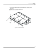
Use the following instructions to route the cables. You will need to route the cables
before installing the deck.
CONNECTING THE DYNO ELECTRONICS AND SHOP AIR
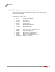
You will need the following parts:
• 318110301 Power Cord
• 42924250 25-pin Cable
• 53415040 Power Supply
• 76199003N Dyno Electronics
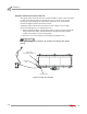
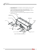
1 Route the 25-pin cable from the dyno electronics to the Breakout board. Connect
the 25-pin cable to the Breakout board.
Refer to page 1-9 for more information on connecting to the dyno electronics.
Refer to page 2-13 for more information on wiring the Breakout board.
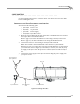
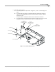
2 Connect the air hose to the T fitting on the dyno brake solenoid.
Note: The air brake comes installed with a hose barb for a 3/8-inch inside
diameter air hose. If your hose does not have an inside diameter of 3/8-inch then
you will need an air hose nipple (1/4-inch NPT) to connect your clean, dry shop
air supply to the dyno. Once the pressure is connected, the air brake is ready to
use.
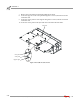
3 Connect the power supply to the dyno electronics. Plug the power supply into
your power source.
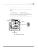
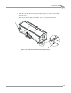
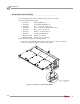
Figure 2-8: Routing the Cables
AD217
power supply for
dyno electronics
breakout board
dyno electronics
dyno electronics
cable
shop air