
Installation Guide User Manual


INSTALLATION
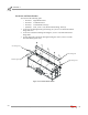
Dyno Installation
Version 4 Above Ground Model 224 Automotive Dynamometer Installation Guide
2-9
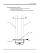
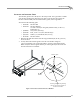
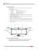
5 Verify the interface guide clears the interface bracket by 3 mm to 6 mm (1/8-inch
to 1/4-inch) as shown in Figure 2-6.
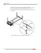
6 Slide the interface guide up until the bottom bolt touches the cross member.
Lower the top bolt down in the slots until it touches the cross member.
7 Tighten the hardware securing the interface guide to the lift cross member.
Note: The lower and upper interface guide mounting bolts should touch the lift
cross member.
8 Raise and lower the lift several times to make sure that the interface guide is
working smoothly. Adjust the interface guide if needed.
9 Verify the lift can be lowered down to floor level.
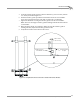
Figure 2-6: Verify Distance Between Interface Guide and Interface Bracket
interface guide on
cross member
interface bracket
on dyno
3 mm to 6 mm
(0.125" to .250")