
Manual


Model 224 Pit Eddy Current Brake Installation and User Guide
Index-i
I
NDEX
25-pin cable, routing 1-18
A
accessing dyno electronics 2-4
adapter plate C-2
B
bearing 1-10
retrofit C-2
brake power cable 1-18
breakout board
control cable 1-19
jumpers 1-20
speed pick-up cable 1-19
temperature sensor cable 1-19
wiring 1-19
C
cable clamp 2-7
cable routing channels 1-16
calibration arm 2-12
number 2-12
weights 2-14
control cable
routing 1-18
wiring 1-19
conventions 1-3
CPU module power 2-5
D
deck assembly 2-10
document part number 1-1
dyno electronics
accessing 2-4
cable clamp 2-7
E
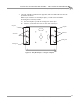
eddy current brake
installation 1-8–1-17
optimal cooling 1-8
parts list 1-4
securing to floor 1-17
theta controller fuses 1-21
unpacking 1-9
wiring breakout board 1-19
end deck assembly 2-9
I
input power cable 1-18
installation requirements
power 1-5, B-2
K
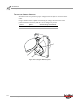
keyed yoke 1-11, 1-12
L
load cell
calibration 2-11–2-16
calibration arm 2-12
calibration number 2-12
calibration weights 2-14
installing 2-2–2-3
routing the cable 2-7
torque gauge 2-16
loading the car 3-2–3-4
M
making a test run 3-10
O
optical RPM sensor 3-5
optimal brake cooling 1-8