
Manual


Model 224 Pit Eddy Current Brake Installation and User Guide
CHAPTER 2
Load Cell Installation
2-2
. . . . . . . . . . . . . . . . . . . . . . . . . . . . . . . . . . .
LOAD CELL INSTALLATION
This section describes how to install the load cell.
PARTS LIST
The following table lists all of the parts included in the Torque Module Installation kit
(P/N 73920007). Check your kit against the parts listed to make sure you have
received all of the parts. If any part is missing, contact Dynojet Technical Support.
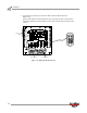
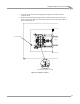
INSTALLING THE LOAD CELL
1 Verify the main dyno power is disconnected.
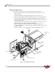
2 Remove the two bolts and nuts securing the existing bar on the eddy current
brake and remove the bar. Set the bolts and nuts aside.
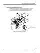
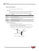
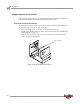
3 Verify the eyelets on the load cell are spaced the same as the bar removed earlier.
Adjust the load cell spacing by loosening the lock nut and turning the eyelet.
Figure 2-1: Verify Load Cell Spacing
part number description quantity
35430899 Weight, 25 lb 4
61319001 Calibration Arm Assembly 1
66114002
or
66104001
Torque Module Sub-Assembly
or
Torque Module High Resolution Sub-Assembly
1
76950505 Torque Cell Assembly, 224 1
76950606 Cable, Input, 224 Torque Rev Sw 1
76950607 Cable, Output, 224 Torque Rev Sw 1
distance must be
the same
eyelet
bar
lock nut