
Manual


EDDY CURRENT BRAKE INSTALLATION
Eddy Current Brake Installation
Version 2 Model 224 Pit Eddy Current Brake Installation and User Guide
1-19
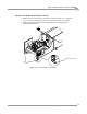
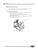
WIRING THE BREAKOUT BOARD
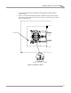
Refer to Figure 1-15 on page 1-20 for Breakout board location information.
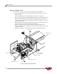
1 Attach the temperature sensor cable to the Breakout board. The temperature
sensor cable has five wires which connect to the wiring block labeled TEMP. This
cable was routed to the Breakout board on page 1-18.
2 Attach the control cable to the Breakout board. The control cable has five wires
which connect to the wiring block labeled LOAD CONTROL. This cable was
routed to the Breakout board on page 1-18.
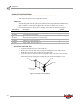
3 Attach the speed pick-up cable to the Breakout board. The control cable has four
wires which connect to the wiring block labeled DRUM 1. This cable was routed
to the Breakout board on page 1-18.
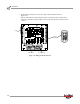
• Green wire connects to G1 • White wire connects to W1
• Black wire connects to B1 • Red wire connects to R1
• Ground (shield) wire connects to S1
• Black wire connects to V- • Red wire connects to V+
• White wire connects to O+ • Green wire connects to O-
• Ground (shield) wire connects to SH
• Red wire connects to R1 • Black wire connects to B1
• White wire connects to W1 • Ground (shield) wire connects to S1