
Installation Guide Owner's manual


INSTALLATION
Routing Cables
Version 3 In Ground Model 224 4WD Automotive Dynamometer Installation Guide
2-11
. . . . . . . . . . . . . . . . . . . . . . . . . . . . . . . . . . .
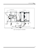
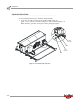
ROUTING CABLES
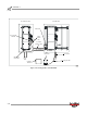
Use the following instructions to identify and route the 224 4WD dyno cables to the
stationary dyno.
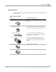
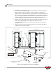
IDENTIFYING THE CABLES
cable brief routing description
A - 25-pin cable connects to the dyno electronics
B - data acquisition (pickup card) cable connects to the pickup card on the stationary 224 or
248 dyno
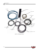
C - multi purpose cable
• C-1 brake power cable
• C-2 load control cable
• C-3 temperature sensor cable
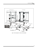
includes the following:
• two pin connector, connects to the two black
wires on the brake solenoid of the stationary dyno
• connects to the EPR on the 248 dyno with
optional prop air; or connects to the theta controller
with optional eddy current brake
• connects to the temperature sensor on the
optional prop air brake on the 248 dyno or to the
temperature sensor on the optional eddy current
brake
D - 224 4WD power cable connects to the power supply
E - dyno movement pendant connects to the dyno movement pendant
F - air hose connects to the air supply