
Installation Guide User Manual

OPTIONAL ACCESSORIES
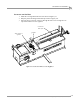
Air Brake
Version 3 Motorcycle Dynamometer Installation Guide
3-13
WIRING THE AIR VALVE ASSEMBLY
The wires that attach to the air valve assembly can be attached in two different places
depending on your dyno’s set up. Wire Set Up 1 is generally for older dynos while
Wire Set Up 2 is for newer dynos.
WIRE SET UP 1
This wire set up is used in older dynos that have an exposed (not in a black box)
terminal strip with only eight terminals. If your terminal strip is in a box and has
sixteen terminals, refer to Wire Set Up 2 on page 14.
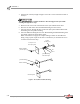
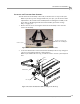
1 Attach the air hose to the coupler and adjust the regulator to 80 psi.
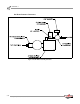
2 Run the two black wires from the air valve to the top two terminals on the left
side, refer to Figure 3-19.
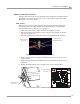
3 Wire the two black extension leads to the top two terminals on the right side.
Figure 3-19: Wire Set Up 1—Terminal Strip Wiring
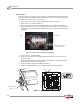
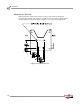
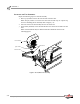
4 Remove the four screws securing the Breakout board and cover. Set the screws
and cover aside.
5 Attach the extension leads to the Breakout board. Orientation of the wires is not
important.
6 Replace the Breakout board cover using the four screws removed earlier.
Figure 3-20: Wire Set Up 1—Breakout Board Wiring
black leads from
the air valve
extension leads to
the Breakout board
two black terminal
strip wires
Breakout board
and cover