
Installation Guide User Manual

Motorcycle Dynamometer Installation Guide
CHAPTER 3
Air Brake
3-6
INSTALLING THE ROTOR/TAPER LOCK ASSEMBLY
When upgrading from a manual brake, the rotor/taper lock assembly and caliper
assembly will already be installed. Proceed to “Installing the Air Cylinder and Master
Cylinder Assembly” on page 3-8.
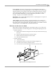
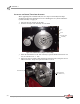
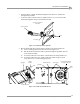
1 Insert the key into the slot on the shaft.
2 Slide the rotor/taper lock assembly on to the shaft.
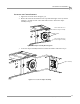
Figure 3-8: Install the Rotor/Taper Lock Assembly
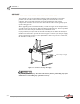
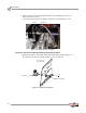
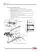
3 Attach the dial indicator to the side of the dyno. Spin the drum and check for run
out; the tolerances are +/- .005".
4 Tighten the taper lock bolts. While tightening, adjust the bolts to keep the run out
within tolerances. Torque the taper lock bolts to 15 ft. lb.
Figure 3-9: Check for Run Out
key
shaft
rotor/taper lock
assembly
dial indicator
taper lock bolts
(two visible here)