
Installation Guide User Manual

HARDWARE INSTALLATION
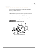
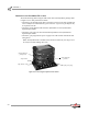
Dynoware EX+ Hardware Stack
Version 3 Motorcycle Dynamometer Installation Guide
2-3
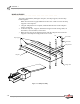
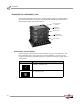
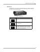
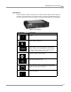
RPM MODULE
The RPM module receives and processes signals from up to two inductive pickups for
measurement of engine RPM. Each input has an automatic gain circuit to compensate
for a wide variance of ignition systems.
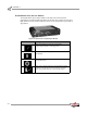
Figure 2-2: RPM Module
LED Indicator Description
The green LED glows when the RPM module is receiving
power.
The amber LED flashes when an RPM signal is detected.
A steady flash rate, proportional to engine RPM, indicates
a good RPM signal.
These connectors are the inputs for both primary and
secondary inductive pickup clips. Either input may be
used with a primary inductive pickup or a secondary
inductive pickup on a single ended coil. Both inputs can
be used for a wasted spark ignition.