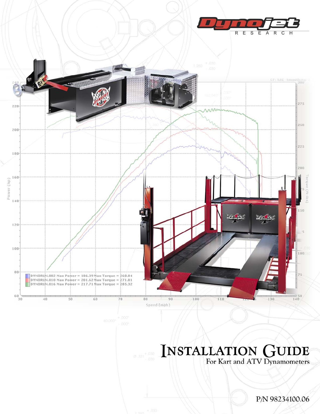
©1993-2005 Dynojet Research, Inc. All Rights Reserved. Installation Guide For the Kart and ATV Dynamometers. This manual is copyrighted by Dynojet Research, Inc., hereafter referred to as Dynojet, and all rights are reserved. This manual, as well as the software described in it, is furnished under license and may only be used or copied in accordance with the terms of such license.
Contents Chapter 1 .......................................................1-1 Installation and Setup Introduction................................................................................. 1-1 Your Dyno Room.........................................................................................1-2 Battery ........................................................................................................1-4 Computer Required ........................................................................
Contents Chapter 4 .......................................................4-1 Basic Dyno Operation Loading the Vehicle .................................................................... 4-2 Connecting the RPM Pickup...................................................... 4-4 RPM Pickup Descriptions ...........................................................................4-5 Connecting the Secondary Inductive Pickup ..............................................4-6 Connecting the Primary Inductive Pickup .
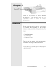
Chapter 1 Kart/ATV Installation and Setup Thank you for purchasing the Dynojet Kart/ATV Dynamometer. information This document will give the needed to install the Dynojet Dynamometer. Introduction Before your dyno arrives there are a few factors to consider. The beginning of this chapter discusses what you will need to provide for your dyno. • Your Dyno Room • 12 volt battery • Computer System The rest of this chapter deals with uncrating, installation and setup of the dynamometer.
Your Dyno Room This section is not meant to imply that a dyno room is essential to repeatable results on a Dynojet dynamometer, though a dyno room with an engine cooling intake fan, exhaust extraction and noise reduction capabilities can add a new dimension to your shop. A proper dyno room design can help to ensure repeatable accurate runs. A good dyno room should: • • • • Minimize noise. Provide a controlled environment for testing. Provide a view window for customers. Be designed with safety in mind.
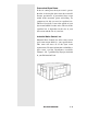
Pressurized Dyno Room If the air coming into the dyno room is greater than the air leaving the dyno room, the room will become pressurized. A pressurized dyno room would make measured power misleading. To compensate for this you need an equalizer box. This box is basically a vent to the outside of your dyno room baffled to reduce noise. The size of the equalizer box is dependent on the size of your dyno room and the size of your fans. Industrial Noise Control, Inc. Industrial Noise Control, Inc.
Battery A vehicle starting system is included with your Dynojet Dynamometer. You will need an automotive battery if you want to use this feature. The dyno is designed to carry a group 24 deep cycle series battery with a minimum of 600 cold cranking amps. Computer Requirements You will need to provide a computer system to run the WinPEP software. WinPEP 7 includes complete documentation in online Help. From the WinPEP 7 menu bar, choose Help WinPEP 7 Help or visit www.winpep.
Uncrate the Dyno Use the following steps to uncrate your dyno. Step 1 Move the crated dyno to a clear area near your dyno room. Step 2 Remove the top of the crate with a suitable pry bar. Note: If you ordered the above ground kit it will be in the top portion of the crate. Remove the kit and top portion of the crate. Refer to chapter 3 (Optional Accessories Installation) for a list of the Above Ground Kits contents and installation instructions.
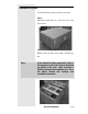
Step 3 Remove the boxes from the crate and verify that they contain the following: G A F H H C E D B DynoWare EX+ system (A) The DynoWare EX+ system is comprised of four modules: the CPU module, the Dynamometer Input/Output module, the RPM module and the Atmospheric module. Mounting Hardware (B) This plastic bag contains the rubber stands for the bottom of the DynoWare EX+. Power Supply and Cable (C) The power supply and cable provides power to the DynoWare EX+. It is 71/2 feet long.
Data Acquisition Cable (E) The data acquisition cable is 20 feet long. This cable connects the Breakout board on the dyno to the DynoWare EX+. Serial Port Cable (F) The serial port cable connects your computer to the DynoWare EX+. This cable is 12 feet long. DynoWare EX+ placement can be important if you run both front and rear wheel drive vehicles. The vehicle operator must be able to see the computer monitor during a run.
Removing the Dyno from the Crate You will have to provide equipment capable of lifting a minimum of 1600 lbs. (725 kg.) to lift the dyno off the crate and position in your dyno room. You will also need a pair of straps capable of supporting 1600 lbs. (725 kg.) to attach to the dyno (Dynojet recommends the single loop style straps). Use the following steps to remove the dyno from the crate. Step 1 Lift the top plate out of the crate and set it aside.
Back panel removed for illustration purposes Install the Battery Install the battery in the battery carriage as shown below: + - Install the red battery cable to the positive post, and the black cable on the negative post Connect the Dyno to the DynoWare EX+ Connect the 25 pin data acquisition cable into the breakout board and hand tighten the screws, as shown below: 25 Pin Data Acquisition Cable from the Dynoware Hardware Stack Document #98234100 1-9
Connect the Shop Air Remove the brake cover if necessary, and then run a 3/8” air hose through the hole in the side of the frame. Push the hose onto the nipple at the regulator, and then secure the air line to the brake line.
Final Assembly Step 1 Secure the dyno to a concrete floor with the supplied “Red Head Anchor Kit”. The feet come bolted on the dyno frame. Mark the (4) holes and then remove the feet. (4) Feet that come attached to the dyno. Using a carbide bit designed for concrete (see instructions included with anchors) , drill four 1/2” holes in the floor where you made your marks. The holes should ideally be as deep as the length of the anchors (approx. 1 5/8”).
Step 3 Use the Set Tool to expand the base of the anchors. Place the small end of the Set Tool into the threaded end of the anchor (threaded end should be up). Drive the Set Tool with a large hammer until the anchor is fully seated. Set Tool Step 4 Replace the (4) feet on the dyno and secure them to the floor with supplied 3/8” hardware. Note: Level the Dynamometer frame by adjusting the bolts that run through the feet and into the frame.
Step 5 Once you have secured the dyno into its final position, remove the (6) 3/8” hex bolts from the top deck. Warning: Never move the dyno without these bolts installed and torqued to 40 ft-lbs. Step 6 Lay the top plate on the top deck of the dyno and secure it with (6) 3/8” truss head bolts. (Above ground applications use (8) 3/8” truss head bolts.
Chapter 2 Hardware Installation DynoWare EX+ The standard dynamometer electronics package is comprised of 4 interconnected modules: System Expansion Connector Atmospheric Sensing Module RPM Module Dynamometer Input/Output Module CPU Module Atmospheric Sensing Module: The atmospheric sensing module measures absolute pressure, air temperature and relative humidity.
RPM Module: The RPM module receives and processes signals from up to 2 inductive pickups for measurement of engine RPM. Each input has an automatic gain circuit to compensate for a wide variance of ignition systems. The green LED glows when the RPM module is receiving power. The amber LED flashes when an RPM signal is detected. A steady flash rate, proportional to engine RPM, indicates a good RPM signal. These connectors are the inputs for both primary and secondary inductive pickup clips.
Dynamometer Input/Output Module: The dynamometer I/O module sends and receives data from the dynamometer and the hand held pendant. The module also contains a buzzer and light which are activated when either the vehicle or dynamometer speed limit is approached. The green LED glows when the dynamometer input/output module is receiving power. The amber LED flashes proportionally to dynamometer drum RPM. This 25-pin receptacle connects to the shielded cable from the dynamometer.
CPU Module: The CPU module contains a 32-bit processor which acquires data from the expansion modules and communicates to the main computer running the WinPEP software. The processor queries the expansion modules to determine their identity and capabilities. The green LED glows when the CPU module is receiving power. The blue LED is lighted when data from the modules is being acquired and saved. One of these connectors is used to communicate to the main computer.
CPU Module: ..... Continued This connector provides a synchronization signal to a 3rd-party data acquisition system. This connector provides 12 Volt DC power to a 3rd-party data acquisition system. This connector accepts 12 Volt DC power from a power supply or battery. The adjacent LED glows bright green when power is properly connected. When this switch is on, power is supplied to all connected modules.
Primary Inductive Pickup Cable (not shown) Remote Switch Breakout Board to DynoWare Cable Cord from Power Supply Computer Serial Port Cable 2-6 Document #98234100
Chapter 3 Optional Accessories Installation Several optional accessories are available for the Dynojet Kart/ATV Dynamometer. This Chapter describes them and give the operator the necessary instructions to install them. Call Dynojet for more information on these optional accessories. Optional Accessories Motorcycle Carriage Gives the operator the ability to easily dyno motorcycles. Available with normal or optional electrically powered carriage adjustment.
Above Ground Kit Contents Front Decks: 2 Deck Assemblies 2 U-Legs 2 Lower Supports Hardware Pack (A) for U-Legs 8 - 3/8" x 21/2" Hex bolts 8 - 5/16" Flat washers 8 - 3/8" Lock washers 8 - 3/8" Nuts Hardware Pack (B) Lower Support to Frame 4 - 3/8" x 3/4" Hex bolts w/ lock tight 4 - 5/16" Flat washers Hardware Pack (C) Front Decks to the dyno 4 - 3/8" Truss head bolts Front Decks Lower Supports A B C U-Legs 3-2 Document #98234100
Rear Deck: 1 - Rear Deck Assembly 3 - Rear Deck Support Arms Hardware Pack (A) Supports to deck 6 - 3/8" x 21/2"" Hex bolts 6 - 5/16" Flat washers 6 - 3/8" Lock washers 6 - 3/8" Nuts Hardware Pack (B) Supports to the dyno 2 - 3/8" x 3/4" Hex bolts w/ lock tight 2 - 5/16" Flat washers Hardware Pack (C)Rear Deck to the dyno 4 - 3/8" Truss head bolts Rear Deck Assembly B A Rear Deck Support Arms C Note: All three supports are interchangeable (Identical) Document #98234100 3-3
Above Ground Installation Step 1 Remove (4) bolts from the rear frame panel. Remove these bolts Step 2 Using the Rear Deck Hardware Pack B, install the Rear Supports on the dyno.
Step 3 Loosen the (6) screws that hold the top plate on the dyno. This will allow you to lineup the holes. and ease installation. Step 4 Place the Rear Deck on the three supports so that the silver tie-down hooks are away from the dyno and the lip deck plate is resting on the dyno. Line up the holes in the dyno frame with the holes in the deck plate and loosely fasten the deck to the dyno, using Rear Deck Hardware Pack C.
Step 5 Bolt the rear deck to the Rear deck supports, using Rear Deck Hardware Pack A. Step 6 Bolt the two Lower Front Deck Supports to the dyno frame.
Step 7 Bolt the two “U” supports to the lower Front Deck Supports. (Front Deck Hardware Pack A) Step 8 There is a right and a left Front Deck. The Deck that has a bolt and bracket welded to the underside is the LEFT and goes on the starter side of the dyno. (This is for the carriage and outrigger option) Place the Front Decks up to the dyno so that the lip of the deck plate is resting on the dyno.
Step 9 Line up the holes in the bottom of the U-Legs with the holes in the Lower Supports and bolt them together, using Front Deck Hardware Pack A. Step 10 Set the rear deck on the supports and secure it just as you did with the front decks. (Rear Hardware Pack A) Step 11 Move the front decks, Rear Deck and Dyno cover as need to align them, and then tighten all the bolts.
Motorcycle Carriage Contents Motorcycle Carriage Outrigger Hardware Pack: 4 - 3/8" x 21/2" Hex bolts 8 - 3/8" Flat washers 4 - 3/8" Nylon Lock Nuts Motorcycle Carriage Installation Step 1 Remove the 5/8" nut and washer from the Outrigger Stud under the left or starter side front deck. (There is also a round pipe shim and washer on the stud.) Slide the Outrigger over the pipe shim and up to the washer. Secure using the 5/ " nut and washer, previously removed.
The Outrigger can now swivel into the lock channel on the deck to secure it for making runs or swivel neatly under the deck to get it out of the way, when not in use. Step 2 Using the 3/8" x 21/2" Hex Bolts, Flat Washers and Nylon Lock Nuts, bolt the carriage to the left front deck. Warning: When using the motorcycle carriage option, install the safety cover on the open drum. Place the lid over the open drum and secure it with two retainer pins.
Chapter 4 Basic Dyno Operation The Dynojet Dynamometer gives state of the art technology, durability, and accuracy that you need. Dynojet’s advanced engineering delivers the precise horsepower measurements a technician needs to make quick and accurate evaluations of engine performance and drive train problems. This chapter includes instructions for basic dyno operation. For more detailed instructions, refer to the WinPEP 7 User Guide. This manual can also be found on your WinPEP CD or at www.dynojet.com.
Loading the Vehicle Use the following steps to load a vehicle on the dyno. 1. Verify your computer is running. Set the dyno brake on by pressing the red button on the hand held pendant. 2. Drive the vehicle onto the dyno and align the vehicle straight with the dyno. 3. Stop the vehicle when the drive axle is centered on the drum. center drive axle on dyno drum 4. When the vehicle is positioned properly on the dyno, shut the engine off. • If the vehicle has an automatic transmission, place it in park.
8. Tighten the four tie-down straps evenly making sure that the drive wheels remain centered on the drum.
Connecting The RPM Pickup Your Dynojet dynamometer includes a primary wire inductive pickup and two secondary wire inductive pickups. These small “clothespin like” inductive pickups are used to sense RPM. An RPM pickup is required if you want to view torque graphs. Generally you will use one secondary wire inductive pickup on a spark plug wire. Vehicles with wasted spark ignition systems may require two secondary inductive pickups.
RPM Pickup Descriptions RPM pickup Secondaries (Non- wasted spark system) Secondaries (Wasted spark ignition system) Primary pickup Document #98234100 description Use one secondary pickup. Unplug the other pickup from the RPM module and set the degrees between plug fires to 720° in WinPEP 7. Use two secondary pickups. Attach one pickup on each spark plug wire on the same coil and set the degrees between plug fires to 360° in WinPEP 7. Attach the primary wire pickup to the primary side of the coil.
Connecting the Secondary Inductive Pickup The secondary inductive pickup cannot be in contact with, or it’s connecting wire be crossing, other engine electrical wires or stray RF interference may result. 1. Clip the secondary inductive pickup around one spark plug wire. Note: On a wasted spark ignition system, two secondary inductive pickup wires may be needed. 2. Route the inductive pickup cable clear of devices that produce electronic noise (spark plug wires, coil wire, coil etc.
Connecting The Primary Inductive Pickup The primary inductive pickup cannot be in contact with, or it’s connecting wire be crossing, other engine electrical wires or stray RF interference may result. 1. Clip the primary inductive pickup around the wire to the primary side of the coil. 2. Route the primary wire cable clear of devices that produce electronic noise to the dyno electronics RPM module. Note: You must ground the vehicle to the dyno for the electronics to function properly.
Pre-run Inspection Perform a vehicle inspection before making a run. • Check the radiator coolant (if applicable) and oil levels. • Check the fuel source. • Rotate the drum and check for rocks caught in the tire tread that could fly out. • Check the tire pressure and tire speed rating. Improperly inflated tires or exceeding the maximum speed rating can result in premature wear or severe tire damage. Make sure the tire has no major deficiencies (cracks in sidewalls, tread life, etc.).
Engine Warm Up Warm the vehicle’s engine and drivetrain before beginning testing. Consistent engine temperatures will assure your runs are repeatable. After Engine Warm Up Always leave the vehicle in neutral (automatic transmission) or in first gear (manual transmission), with the engine off, and make sure the park brake and the dyno brake are on when you get off the vehicle on the dyno. • Fix any fuel, oil, or coolant leaks that may have shown up after engine warm up and check the carburetor for leaks.
Making a Test Run Dyno runs provide safe, reliable road testing right in the shop. The dyno allows you to measure, record, and diagnose performance problems quickly. The dyno combined with WinPEP 7 produces consistent, easily interpretable power graphs. Use the following instructions to ensure repeatable and accurate measurements. 1. Verify the vehicle is secured properly. 2. Place the vehicle in a low gear and release the dyno brake using the hand held pendant. 3. Slowly accelerate the vehicle to 20 m.p.h.