©1997-1999 Dynojet Research, Inc. All Rights Reserved. Eddy Current Brake Installation Guide for Model 168/178/188/198 Dynamometers. This manual is copyrighted by Dynojet Research, Inc., hereafter referred to as Dynojet, and all rights are reserved. This manual is furnished under license and may only be used or copied in accordance with the terms of such license. This manual is furnished for informational use only, is subject to change without notice, and should not be construed as a commitment by Dynojet.
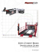
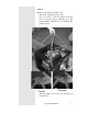
Eddy Current Brake Installation Guide This manual is designed to help the user install the Eddy Current Brake optional hardware for Dynojet’s model 168 / 178 / 188 / 198 Dynamometers. Uncrate Step 1 Remove the top and sides of the crate and remove retarder cover. - Remove (4) bolts that secure the retarder cover. - Remove the Retarder Safety Cover. - Unclamp the retarder from the Retarder Cover. - Remove the hardware box and the hood extension from the crate.
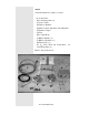
Step 2 Verify the hardware contents as follows: - (A) Control Box - (B) Connecting Arms (2) - (C) Power Cable - (D) Remote Pendant - (E) Male Coupler (Mounted on the Retarder) - (F) Female Coupler - (G) Key - (H) Coupler Bolts - (I) Rubber Mounts (4) - (J) Rubber Grommets (2) - (K) Plastic Ties (4) - (L) 3/8" Nuts, Bolts and Lockwashers for Connecting Arms (4) Refer to the picture below.
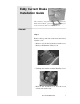
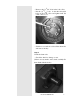
Step 3 Remove the retarder from the crate. - Unbolt the retarder from the crate. - Use loop straps to lift the retarder from the crate. Loop the straps around the top of the retarder frame so that they cross as shown in the pictures below. Correct Incorrect - Lift the retarder out of the crate and place it near the dyno.
Prepare Dyno Step 1 Unbolt the top deck and then remove it. Step 2 Remove the brake cover (if applicable) - Using a 9/16" socket, open or box end wrench, remove the four bolts, (2) each side, that secure the cover to the dyno. Step 3 Disconnect the battery.
Remove the Brake Remove the existing dyno brake (if applicable). Step 1 Remove the brake lines and master cylinder assembly. Brake Removal. - Disconnect all air lines and brake lines from the dyno. - Disconnect brake electrical wires: - Remove the cover on the wire terminal box and disconnect the air valve wires from the breakout board. - Remove the four hex head bolts from the air canister assembly and remove it. The bolts come through from the other side of the center frame section.
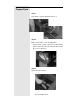
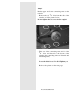
Step 2 Remove the 4 bolts holding the brake pad assembly (caliper assembly). Loosen the brake pads and remove the assembly. Do not put the bolts back into the dyno frame as the holes will be used to fasten the retarder to the dyno. Step 3 Remove the rotor. - Loosen the set screw above the keyway in the drum axle using a 3/16" Allen wrench.
- Remove the (3) 5/16" bolts in the lock collar. - Put the (3) 5/16" bolts in the three threaded holes in the lock collar and tighten until the collar comes loose. - Slide the rotor and lock collar off the drum axle and remove the key. Step 4 Check the drum axle. - Check the shaft for damage or rust. (If there are any marks on the shaft, carefully file them flush with the shaft.
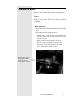
Step 5 Put the upper and lower connecting arms on the retarder. - Remove the (8) 3/8" bolts from the side of the retarder, as in the picture below. Do not tighten the set screw in the coupler! - Take one of the connecting arms and 4 of the 3/ " bolts and fasten it to the bottom of the 8 retarder (the connecting arms are identical and interchangeable). Leave the bolts loose! Do Not Tighten yet. Refer to the picture on the next page.
- Take the other connecting arm and 4 of the 3/8" bolts and fasten it to the top of the retarder. Leave the bolts loose! Do Not Tighten yet.
Step 6 Put the coupler on the dyno. - Put a key in the keyway. - Slide the coupler over the key on the axle.
Connect The Retarder to the Dyno Step 1 Place the retarder next to the dyno so that the 8 holes in the connecting arms meet the 8 holes in the dyno frame. Step 2 Using eight 3/8"x3/4" bolts and washers (supplied), bolt the connecting arms to the dyno. Leave the bolts loose! Do Not Tighten yet. Note: The bolts that secure the arms to the dyno should have blue lock tight on them. Note: You must use the 3/8 “ x 3/4” bolts with a flat washer when connecting the arms to the dyno.
Step 3 Align the retarder with the dyno. - Remove the top bolt of the torque arm so that the middle of the retarder can swivel. - Place a straight edge across the apex of the drum and across the retarder. (Swivel the middle of the retarder as necessary for clearance.) - Measure down to the collars on the axle shaft of the retarder (not the black bearing locking collars!). Shim the retarder or the dyno until the collars are 7 19/32" (19.288 cm) down from the top of the drum on the dyno +/- 1/16" (1.58 mm).
Step 4 Torque all the bolts on the connecting arms to the dyno and to the retarder to 400 in. lbs. (45 N m) Recheck the height as in Step 4 to ensure that nothing has moved.
Step 5 Couple the retarder to the dyno. - Put the bolt back in the torque arm and tighten to 40 in. lbs.(4.5 N m). (Swivel the middle of the retarder as necessary.) - Slide the coupler on the dyno over the coupler on the retarder so that the three holes in each of the couplers line up. - Bolt the couplers together with three 3/8" coupler bolts and tighten to 396-444 in. lbs. (45-50 N m). - Tighten the set screws in the couplers to 260290 in. lbs. (29-33 N m).
Control Box Installation and Wiring Step 1 Locate the (4) holes in the dyno frame and install the (4) rubber mounts. Use the star washers and screws to secure the mounts. (4) rubber mounts on the inside of the dyno frame. Step 2 Mount the Control Box to the dyno frame. Secure the Control Box with the nuts provided. The plugs on the Control Box should be oriented upward.
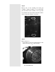
Step 3 Use a 3/8” nut to secure a wire loop to the frame bolt. Run the wire from the Control Box through the wire loop and then through the grommet in the frame. Leave the nut loose, you will run another wire through the loop later. Step 4 Wire the Control Cable from the Control box to the Breakout board. - The control cable has 5 wires. They connect to the wiring block on right side of the breakout board labeled “ -LOAD CONTROL - “. The black wire connects to V-. The red wire connects to V+.
- The jumpers circled in the picture (previous page) may need to be changed to look like the drawing below. Step 5 Wire the Temperature Probe wires to the breakout board. - The temperature cable has 5 wires. They connect to the wiring block on the bottom of the breakout board labeled “ - TEMP- “. The green wire connects to G1. The white wire connects to W1. The black wire connects to B1. The red wire connects to R1. The ground wire connects to S1. See picture below.
- The finished Breakout Board Wiring should look like this: Data Acq. Cable Control Cable Temp Probe Cable Step 6 Run the Input Power Cable through the grommet below the Control Box. (See picture on next page) 18 Note: The Eddy Current Brake is setup to run on 120 volts / 20 amps / 60 Hz for U.S. or 220 volts / 10 amps / 50 Hz for European Note: The voltage source must be capable of handling a minimum of 20 amps U.S. or 10 amps European.
Step 7 Attach the Input Power Cable to the Control Box. Step 8 Run the Retarder Power Cable from the Retarder through the hole with the grommet on the side of the Dyno.
Note: See Appendix A if you must change the plug on the Input Power Cable. Note: The Eddy Current Brake is setup to run on 120 volts / 20 amps / 60 Hz for US or 220 volt / 10 amps / 50 Hz for European. Warning!! The voltage source and power plug must be capable of handling a minimum of 20 amps. US or 10 amps European. Step 9 Attach the Retarder Power Cable to the Control Box. Step 10 Run the Retarder Power Cable along the edge of the frame.
Install The New Retarder Cover Step 1 Remove the (4) screws that hold the cover on the Wire Terminal Box. Remove the cover on the wire terminal box and set it aside. Step 2 Using a small flat head screwdriver, loosen the screws that retain the Starter Remote leads, and pull the leads out of the box. Step 3 Remove the wire restraint from the side of the Retarder Cover. Unscrew the restraint into two halves, then slide the Starter Remote leads through the two halves.
Run the Starter Remote lead through the strain relief. Step 4 Carefully position the retarder cover to the dyno and then reattach the starter remote wires. See picture on previous page for wiring detail. Step 5 Use the four bolts from the old cover to bolt the new Retarder Cover to the dyno.
Step 6 Use the two bolts and clips, previously removed, to bolt the cover to the retarder. Step 7 Install the top deck that was removed earlier. Step 8 Use the four allen head bolts, previously removed, to bolt the retarder cover to the hood.
Warning: Never operate the dyno with these covers removed! Notes: 24 Document #98232100
Appendix A Note: The Eddy Current Brake is setup to run on 120 volts / 20 amps / 60 Hz for US or 220 volt / 10 amps / 50 Hz for European. Warning!! The voltage source and power plug must be capable of handling a minimum of 20 amps. US or 10 amps European. If you must replace the power plug, be sure to adhere to the specification above.