
User's Manual
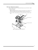
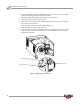
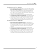
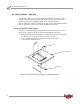
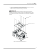
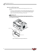
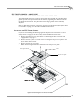
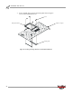
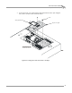
Table Of Contents
- Cover
- Copyright
- Table of Contents
- Air Brake and EEC Kit Installation
- Introduction
- Air Brake
- Removing the Drum Module Hood, Side Drum Cover, Center Panel, and Tire Carriage
- Removing the Pit Cover Plate and Upright Brace
- Installing the Air Brake Assembly
- Routing the Air Brake Cable
- Connecting the Shop Air-200i/250i
- Connecting the Shop Air-200iP/250iP
- Adjusting the Brake Pad Clearance
- Final Adjustments and Tests-200i/250i
- Final Adjustments and Tests-200iP/250iP
- EEC Finger Guards-200i/250i
- EEC Finger Guards-200iP/250iP
- Door Safety Switch
- Replacing the Drum Module Hood, Side Drum Cover, Center Panel, and Tire Carriage-200i/250i
- Replacing Pit Cover Plates and Upright Brace-200iP/250iP
Air Brake and EEC Kit Installation Guide for 200i/250i and 200iP/250iP Motorcycle Dynamometers
AIR BRAKE AND EEC KIT
EEC Finger Guards—200i/250i
22
ADJUSTING THE EEC FINGER GUARDS
Once the drum module hood is installed, the EEC finger guards will need to be
adjusted.
1 Loosen the 1/4-20-inch pan head screws and adjust the EEC finger guards so they
are 0.16 cm to 0.64 cm (0.0625 in. to 0.25 in.) from the drum. Tighten the screws.
2 Check the EEC finger guards regularly to verify the clearance has not changed.
Note: For clarity, the retarder and carriage are not shown.
Do not operate the dynamometer without the EEC finger guards properly
installed. The gap between the finger guards and the drum must be less than
0.64 centimeters (0.25 inches).
Figure 22: Adjusting the EEC Finger Guard Clearance
adjust clearance
adjust screw