
User's Manual
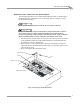
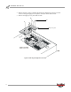
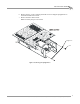
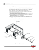
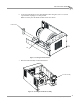
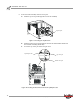
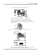
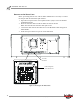
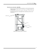
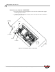
Table Of Contents
- Cover
- Copyright
- Table of Contents
- Air Brake and EEC Kit Installation
- Introduction
- Air Brake
- Removing the Drum Module Hood, Side Drum Cover, Center Panel, and Tire Carriage
- Removing the Pit Cover Plate and Upright Brace
- Installing the Air Brake Assembly
- Routing the Air Brake Cable
- Connecting the Shop Air-200i/250i
- Connecting the Shop Air-200iP/250iP
- Adjusting the Brake Pad Clearance
- Final Adjustments and Tests-200i/250i
- Final Adjustments and Tests-200iP/250iP
- EEC Finger Guards-200i/250i
- EEC Finger Guards-200iP/250iP
- Door Safety Switch
- Replacing the Drum Module Hood, Side Drum Cover, Center Panel, and Tire Carriage-200i/250i
- Replacing Pit Cover Plates and Upright Brace-200iP/250iP
INSTALLATION GUIDE
Air Brake
Version 1 Air Brake and EEC Kit Installation Guide for 200i/250i and 200iP/250iP Motorcycle Dynamometers
13
8d Secure the bottom clevis pin with a hairpin cotter.
Figure 13: Securing the Bottom Clevis Pin with a Hairpin Cotter
9 Loosely secure the brake caliper stop to the brake bracket using two
3/8-16 x 3/4-inch bolts with lock washers and two 5/16-inch flat washers.
Note: For clarity, the drum, parts of the dyno frame, and the air brake assembly
spring are not shown.
Figure 14: Securing the Brake Caliper Stop
Note: Before proceeding with the rest of the air brake installation it is necessary
to connect the shop air and check the brake pad clearance.
bottom clevis pin
hairpin cotter
brake caliper stop
brake bracket