
User's Manual

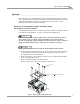
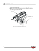
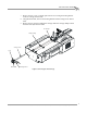
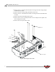
Table Of Contents
- Cover
- Copyright
- Table of Contents
- Air Brake and EEC Kit Installation
- Introduction
- Air Brake
- Removing the Drum Module Hood, Side Drum Cover, Center Panel, and Tire Carriage
- Removing the Pit Cover Plate and Upright Brace
- Installing the Air Brake Assembly
- Routing the Air Brake Cable
- Connecting the Shop Air-200i/250i
- Connecting the Shop Air-200iP/250iP
- Adjusting the Brake Pad Clearance
- Final Adjustments and Tests-200i/250i
- Final Adjustments and Tests-200iP/250iP
- EEC Finger Guards-200i/250i
- EEC Finger Guards-200iP/250iP
- Door Safety Switch
- Replacing the Drum Module Hood, Side Drum Cover, Center Panel, and Tire Carriage-200i/250i
- Replacing Pit Cover Plates and Upright Brace-200iP/250iP
Air Brake and EEC Kit Installation Guide for 200i/250i and 200iP/250iP Motorcycle Dynamometers
AIR BRAKE AND EEC KIT
Air Brake
6
10 Remove the two 5/16-inch bolts and washers securing each of the carriage clamps
and shims and set aside.
11 Remove the three carriage clamps and shims and set aside.
12 Remove the two 5/16-inch bolts and washers securing the nut block and shim and
set aside.
13 Remove the nut block and shim and set aside.
14 Remove the six 1/4-20 x 5/8-inch pan head screws securing the center panel to the
dyno carriage and set aside.
15 Remove the center panel and set aside.
Figure 4: Removing the Center Panel
screw
center panel
carriage
clamp
washer
bolt
shim
nut block