Installation Guide For the Automotive Dynamometer 224-4WD Model Upgrade Dynojet® Research Inc.
© 1993, 1994, 1995, 1996, 1997,1998 and 1999 Dynojet Research Inc. All Rights Reserved. Dynojet Installation Guide for use with Dynojet’s Automobile Dynamometer model 248. This manual is furnished under license and may only be used or copied in accordance with the terms of such license. The information in this manual is furnished for informational use only, is subject to change without notice, and should not be construed as a commitment by Dynojet Research Inc. Dynojet Research Inc.
Contents Chapter 1 ..............................................1 - 1 Initial Setup and Requirements Introduction ............................................................................1 - 1 Dyno Placement ....................................................................1 - 2 DynoWare EX+ Placement ....................................................1 - 3 Computer Placement ............................................................1 - 4 Requirements to Unload Truck................................
Chapter 3 ..............................................3 - 1 Installing the 224-4WD Dynamometer Track Placement......................................................................3 - 1 Wiring ......................................................................................3 - 5 Connect the Air Supply..........................................................3 - 8 Prop-Air Wiring........................................................................3 - 9 Testing the Movement of the Dyno .............
Chapter 1 Initial Setup and Requirements Thank you for purchasing the Dynojet Automotive Dynamometer. This document will give you the information you need to install the 224-4WD Dynojet Dynamometer (pit model). If you have any questions please call Dynojet at (800) 992-4993. Introduction Before installing your Dynojet Dynamometer, there are a few factors to consider.
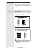
Dyno Placement The first step to installing your Dynojet Dynamometer depends on the location of your existing 248 dyno. It can go in front of, or behind the 248 dyno. Note: The Dynamometer drums can rotate in either direction Choose the Dyno placement that best matches your shop. 224 4WD 248 This image represents a 224-4WD dyno near the garage door. 248 224 4WD This image represents a 224-4WD dyno away from the garage door.
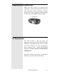
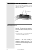
DynoWare EX+ Placement The DynoWare EX+ system is comprised of four modules: the CPU module, the Dynamometer Input/Output module, the RPM module and the Atmospheric module. The Dynamometer Input/Output module connects to the 224-4WD dynamometer. (A 20 foot (6.1 meter) long cable is provided.) The CPU module connects to a personal computer. (A 12 foot (3.7 meter) long cable is provided.) RPM Pickups and a Hand Held Pendant also connect to the modules.
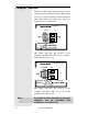
Computer Placement The driver of the vehicle must be able to view the computer monitor and the DynoWare EX+ during a run. If you will be running both front and rear wheel drive vehicles you will need to find a way for the driver to see them both. Facing Door 224-4WD 248 This image represents the location of the computer and DynoWare EX+ for a car that is backed into the dyno room.
Requirements to Unload Truck When your dyno arrives, you must provide equipment to unload the dynamometer from the truck, with skids or forks a minimum of 6 inches wide by 6 feet long. It must be capable of lifting and moving at least 8000 pounds (3642 KG). 224-4WD Dyno Pit Requirements You must provide a dyno pit. Dyno pit dimensions are provided in the technical drawing 4WD Dyno Specifications. Be sure to contact your local contractor for code specifications before digging a pit.
Requirements to Install the Dynamometer When you install the dynamometer, you need equipment capable of lifting and moving at least 8000 pounds (1821 KG). 224-4WD Dyno Other Requirements Shop Air - The dyno air brake requires a 3/ " air hose with a minimum pressure of 8 100 psi. ! You must provide a 3/8" air line that will reach both the 224 and 248 Dynamometers. Computer - You must provide compatible computer and printer.
! Pentium P5-100 or faster Pentium computer ! Windows 95 ! 800 megabyte HD ! Eight megabytes of RAM ! 640 x 480 (SVGA) 16k color video ! One high density floppy disk drive (3 1/2") ! Color Printer (HP Deskjet color series recommended) Optional Accessories Extended Pendant Cable 40 foot (12.
Uncrating the Dynos Step 1 Use a crowbar or the like to remove the plywood shipping shell from the 224 Dynamometer. ! Remove the top of the crate. ! Remove the sides of the crate.
Contents Railway Components: (2) Rails (2) Sets, Grating Support Channels, Front and Rear (2) Rail Assembly Ends (3) Rail Ties (10) Rail Tie Clips Document #98210104 1-9
(2) Rail Clamps (4) 3/8 -16 Shoulder Bolts (4) .220” Thick 1/2” Washers (2) Idler Sprockets (2) 1/2”-13 x 1 1/2” UNC Bolts (2) .
Grating Components: (2) Center Covers (2) Side Grates (4) Front / Rear Grates Document #98210104 1 - 11
Boxes Containing: ! ! (4) Ratchet Straps w/ Sleeve (4) Axle Straps Bolt Pack #1: ! ! ! ! ! ! ! ! (20) 3/8-16 x 1 Truss Head Bolts (6) 3/8-16 x 3 Truss Head Bolts (46) Concrete Anchors (34) 3/8-16 x 1 UNC Bolts (10) 3/8-16 x 1 1/2 UNC Bolts (10) 3/8-16 x 2 UNC Bolts (54) 3/8 Flat Washers (54) 3/8 Lock Washers Ground Hooks: ! ! ! ! ! 1 - 12 (4) Ground Hook (Baseplate and Hook) (8) Concrete Anchors (8) 3/8" - 16 UNC x 1 Bolts (1) Anchor Instructions (1) Anchor Set Tool Document #98210104
Electronic and Miscellaneous Hardware: ! (1) Hardware Stack ! (1) Hardware Stack Mounting Kit ! (1) Sample / Brake Pendant ! (2) Power Cables ! (1) Power Supply ! (1) Power Supply (modified) ! (1) Primary Inductive ! (2) Secondary Inductives ! (1) Computer Cable, 9 Pin ! (1) Computer Cable, 25 Pin (installed) ! (27”) Airline Hose ! (2) Barbed Fittings ! (1) Air Solenoid Assembly or Prop.
Pit Covers (248 Dyno) and Hardware: (1) Left Interface Plate (1) Center Interface Plate (1) Right Interface Plate ! 1 - 14 (7) 3/8” UNC x 1" Truss Head Bolts Document #98210104
Notes: Document #9810104 1 - 15
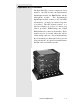
Chapter 2 Hardware Installation DynoWare EX+ The standard dynamometer electronics package is comprised of 4 interconnected modules: System Expansion Connector Atmospheric Sensing Module RPM Module Dynamometer Input/Output Module CPU Module Atmospheric Sensing Module: The atmospheric sensing module measures absolute pressure, air temperature and relative humidity.
RPM Module: The RPM module receives and processes signals from up to 2 inductive pickups for measurement of engine RPM. Each input has an automatic gain circuit to compensate for a wide variance of ignition systems. The green LED glows when the RPM module is receiving power. The amber LED flashes when an RPM signal is detected. A steady flash rate, proportional to engine RPM, indicates a good RPM signal. These connectors are the inputs for both primary and secondary inductive pickup clips.
Dynamometer Input/Output Module: The dynamometer I/O module sends and receives data from the dynamometer and the hand held pendant. The module also contains a buzzer and light which are activated when either the vehicle or dynamometer speed limit is approached. The green LED glows when the dynamometer input/output module is receiving power. The amber LED flashes proportionally to dynamometer drum RPM. This 25-pin receptacle connects to the shielded cable from the dynamometer.
CPU Module: The CPU module contains a 32-bit processor which acquires data from the expansion modules and communicates to the main computer running the WinPEP software. The processor queries the expansion modules to determine their identity and capabilities. The green LED glows when the CPU module is receiving power. The blue LED is lighted when data from the modules is being acquired and saved. One of these connectors is used to communicate to the main computer.
CPU Module: ..... Continued This connector provides a synchronization signal to a 3rd-party data acquisition system. This connector provides 12 Volt DC power to a 3rd-party data acquisition system. This connector accepts 12 Volt DC power from a power supply or battery. The adjacent LED glows bright green when power is properly connected. When this switch is on, power is supplied to all connected modules.
Primary Inductive Pickup Cable (not shown) Remote Switch Breakout Board to DynoWare Cable Cord from Power Supply Computer Serial Port Cable 2-6 Master Document #98226100
Chapter 3 Installing the 224-4WD Dynamometer Now that you have the Dyno unpacked, you may begin the installation of the Dynamometer. Track Placement The dyno is designed to roll back and forth on the track. The track must be anchored to the floor using cement anchors. Step 1 Lay out the track as shown in figure 1 (Appendix A). Step 2 Place the rail clamps over the rails before placing the two end rail supports.
Step 3 The track assembly should be 1.975” away from the pit wall. (closest to the 248 dyno) 1.975” Step 4 Line up the centerline of the track assembly with the centerline of Model 248 Chassis Dyno. Step 5 Check the square of the track assembly (measure from corner to corner). Note: Be sure that the track is fully seated under the rail clamp. See Figure 2 in Appendix A. The distance between the inside of the rails should be: 72.5” + - 0.06” 72.
Step 6 Install the cement anchors and 11/2” bolts. The bolts should secure the track and track tie. When the bolts are tightened down, check the square of the track again. See Figure 3 in Appendix A. Note: See page 3-36 for anchor installation. Step 7 Place two straps (capable of supporting a minimum of 4000 lbs or 1820 KG ) around the drums. Position the straps so that they are on the knurled surface of the drum away from the brake surface. Step 8 Lower the dyno onto the tracks.
Step 9 Install the two rail clamps with the 3/8” bolts and spacers.. Once the bolts are tight, roll the dyno back and forth to ensure the rail clamps are not binding. Note: Move the Rail Clamps up and down to ensure that they are free to move. If the clamps are binding ,you will need to loosen the allen head bolts. Be sure to add thread lock to ensure that the bolts are secure. Step 10 Secure the cable carrier to the rail tie with two 1/4” button head screws and lock washers.
Wiring Note: The 248 Dyno comes with a “Standard” brake, but Dynojet does offer an optional “Prop-Air” brake. For convenience, both installation procedures are outlined in the next few pages. Follow each step carefully, some steps are designated as “Prop Air only”. Step 1 Lay out the cables to become oriented with their placement. F A B E D C Note: Run the cables / hose through the conduit to the outside of the pit.
(A) - 25 Pin Cable (20’) - Connect the 25 Pin Cable to the Hardware Stack. (B) - Data Acquisition Cable (40’) - Connect the Data Acquisition Cable to the Pick Up Card on the 248 dyno. (Run into 248 pit) (C) - Multi-Purpose Wire - Brake Power Cord (40’) - Connect to the spade connector on the new 248 air assembly. - Prop Air Cable (40’) - optional for load control system, attaches to the EPR. - Temp Sensor Cable - optional, part of the Prop Air load control system.
! Install the temperature sensor so it is approximately 3" from the surface of the drum. Top View ! Run the Temperature Sensor Cable (pg.3-22, letter H) from the 224-4WD Dyno and plug it into the connector on the end of the Temperature Sensor. Step 4 Run the data acquisition cable (pg 3-22, letter B) from the Model 224-4WD dyno, and plug it into the the pick-up card on the 248 dyno.
Connect the Air Supply Step 1 Connect your shop air to the dyno. ! Mount the Air Pressure Regulator on the wall in the shop with the bracket provided. ! Connect a supply air hose to the inlet of the regulator from your shop air supply. Note: Make sure the arrow on the regulator is the same as the direction of the air flow! ! Connect a 3/8" air hose to the outlet side of the regulator.
Prop-Air Wiring This section is for the Prop-Air Braking System, Standard Brake customers should skip this section. Step 1 Connect the Prop-Air Cable (pg. 3-22, letter C) to the EPR. ! You will need to remove the clear plastic cover from the EPR. ! Plug the Prop-Air Cable into the terminal block on the EPR. EPR Prop-Air Cable Step 2 Connect the Modified Power Supply wire to the 224-4WD Power Cord (pg. 3-22, letter D) with the two pin connector.
Testing the Movement of the Dynos Step 1 Connect the remaining wires to the Hardware Stack as described in Chapter 2, page 2-5. Step 2 Turn the Hardware Stack on. Step 3 Press the red button on the Pendant, it should light up, this indicates that the brakes are activated. Cycle the brakes a few times by pressing the red button to ensure that they work properly. Note: The red button will control the brakes on BOTH dynos. Step 3 While the brakes are on, press the “In” button on the Control Pendant (pg.
Final Assembly Step 1 Install the sprockets with 1/2” bolts and spacers. Note: Be sure that you have the spacers oriented properly, see the picture below. Spacers ! Route the chain so that it wraps around the drive sprocket and under each idler sprocket.
Step 2 Attach the chain to the end rail tie on the front and back. Secure the chains with 1/2” lock washers and nuts. Step 3 Assemble the C-channel Cross Brace with 3/ ”x1” bolts, but don’t tighten them down yet. 8 Step 4 Place the two assembled cross members in the pit. See Figure 6 in Appendix A. Note: 3 - 12 Move the dyno back and forth from front to back. The dyno should not touch the cross members, if it does, you’ll need to move the cross members for clearance.
Step 5 Adjust the width of the C-channel assembly until it is as wide as the pit. Secure the left and right sides of the C-channel with the cement anchors. When the sides are anchored, tighten down the center bolts. Step 6 Move the dyno through its full range of motion. Be sure that the dyno is free to move and there are no obstructions. When you press the “in” or “out” button on the pendant you should hear the air release to unlock the rail clamps. After a few seconds the dyno should begin to move.
Install the Dyno Covers Use the following steps to install the dyno cover(s): Step 1 Check the anchor bolts and lateral supports to make sure they are tight. Install the dyno cover. Step 2 Install the pit cover plates over your dyno. A sample layout drawing for the auxiliary covers is provided in Figure 7, Appendix A.
Setting Up the 224-4WD Grating Note: Refer to Appendix A, Figure 8 to become familiar with the layout of the grating. Step 1 Place the Grates on the motor side of the dyno so the long lip is towards the drum. Secure the grates to the dyno with (2) 3/8” x 3” truss head bolts, but do not tighten yet. Motor Step 2 Place the Center Plate on the Grates and secure it with (8) truss head bolts (the Center Plate is secured to the dyno with (1) 3/8” x 3” truss head bolt).
Step 3 Set up the “non-motor side” Grates in the same fashion as did for the “motor-side” grates. Also, attach the Center Plate, and then tighten everything down when complete. Step 4 Set up the side grates. ! Lay the side grates on the side of the dyno with the bolt holes towards the outside. The side grates should be oriented with a 1” gap between the grates mounted to the dyno. ! Use concrete anchors to secure the side grates to the concrete surrounding the dyno.
Ground Hooks Ground hooks are points at which you can connect the straps that hold down the car that is being tested. This keeps the vehicle from sliding side to side or off the drum of the dyno during a run. Forward and Back Shifting Side To Side Ground Hook Installation Hardware: Ground Hook: 10 Rings 10 Ring Plates Anchors: 20 Drop-In Anchors Bolts: 20 1" x 3/8" UNC Grade 5+ Setting Tool: Used for expanding the anchors.
Drop-In Anchor A drop-in anchor is a heavy duty internally threaded anchor used to bolt the ground hooks onto a concrete floor. Ground Hook Placements The placement of the ground hooks are provided with the “Pit Dimensions” drawing. Your Sales Contact can provide these for you.
Installing Ground Hooks Step 1 Using an Impact Drill, drill the two holes in the cement at each location on the drawing in Appendix A. (Use a ring plate as a template for the precise hole placement.) You will need a 1/2" drill bit to drill a hole to a minimum depth of 1 5/8". Clean the cuttings and debris from the hole. Clean out Debris Note: (1) The use of a carbide drill bit is recommended for the installation of this anchor. (2) Do not use core drills to drill hole for this anchor.
Step 3 Expand the anchor with the setting tool. The anchor is properly expanded when the shoulder of the setting tool is flush with the anchor. Step 4 Bolt the ground hooks onto the anchors to complete the ground hook installation.
Notes: Document # 98210104 3 - 21
Appendix A 248 Dyno Figure 1 Revision A 4-12-00 Document #98210104 Appendix A - 1
Figure 2 Appendix A - 2 Document #98210104
Figure 3 Document #98210104 Appendix A - 3
Figure 4 224 Dyno Rail Brake Clamp 248 Dyno Rail Brake Clamp Appendix A - 4 Document #98210104
Side View Motor Side of 224-4WD 248 Dyno Figure 5 Document #98210104 Appendix A - 5
Figure 6 Plastic Flush w/ Top of Pit Side View Appendix A - 6 Document #98210104
Figure 7 Pit Cover Layout Top View Document #98210104 Appendix A - 7
Figure 8 224-4WD Grate Layout Top View Appendix A - 8 Document #98210104
224-4WD TROUBLE SHOOTING GUIDE: 1) Make sure the following is turned on: Hardware stack EX+, Computer, Dyno brake (red button on pendent in on). Press IN/OUT button on movement pendent to see if dyno moves. If not proceed to step two 2) Check to see if relay is working. When the brake button on the dyno pendent (red lighted button) is turned off and on the relay should "click". If this does not happen go to step 2A, if this is happening go to step 3.