
Pest Control Equipment User Manual


Control Panel Interface Installation and User Guide
CHAPTER 1
Introduction
1-2
. . . . . . . . . . . . . . . . . . . . . . . . . . . . . . . . . . .
INTRODUCTION
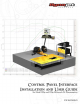
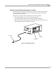
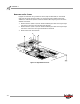
The Control Panel Interface (CPI) consists of a main control board which is mounted
in an external box for a pit dyno or retrofit. This board provides switching and control
of many functions within the dyno. The front panel of this board is accessible through
the door on the external box. The user interface is through the Control Panel which is
normally mounted on the side of the monitor tray. The Control Panel allows the user
to control the following items:
• Optional AFR Air Pump
• Optional High Pressure Blowers
• Optional Motorized Carriage
•Starter
• Optional Wheel Clamp
The CPI main control board has an on board microprocessor which reads the user
input from the Control Panel, monitors interlock and E-Stop inputs, and controls the
various dyno outputs. The CPI is powered internally from the main power that is
provided to the dyno. The power supplied is 240VAC 50 or 60 Hz.
CONVENTIONS USED IN THIS MANUAL
The conventions used in this manual are designed to protect both the user and the
equipment.
TECHNICAL SUPPORT
For assistance, please contact Dynojet Technical Support at 1-800-992-3525, or write
to Dynojet at 2191 Mendenhall Drive, North Las Vegas, NV 89081.
Visit us on the World Wide Web at www.dynojet.com where Dynojet provides state of
the art technical support, on-line shopping, 3D visualizations, and press releases
about our latest product lines.
example of convention description
The Caution icon indicates a potential hazard to the
dynamometer equipment. Follow all procedures
exactly as they are described and use care when
performing all procedures.
The Warning icon indicates potential harm to the
person performing a procedure and/or the
dynamometer equipment.