
Pest Control Equipment User Manual


Control Panel Interface Installation and User Guide
CHAPTER 2
Maintenance and Troubleshooting
2-10
TROUBLESHOOTING POWER DISTRIBUTION ASSEMBLY FUSES
Fuses F3 and F4 fuse the 240VAC as it enters the CPI board. One fuse for each leg of
the 240VAC. If either of these fuses are blown there will be no power to the CPI board
or any of the accessories. The Status Light on the board as well as the button panel
will be off. Replace with a 5x20 mm 3A fast blow fuse.
Fuse F5 provides protection for the DC power that is produced by the on board
power supply and routed to the CPI board. If this fuse is blown there will be no
power to the CPI board or any of the accessories. The Status Light on the board as
well as the button panel will be off. Replace with a 5x20 mm 3A fast blow fuse.
Fuse F6 provides protection for the power that is provided for the 12VDC accessories
from the dyno owner installed car battery. This also protects the charging circuit to
the battery. If this fuse is open the motorized carriage and the wheel clamp will not
function. Replace with a 15A mini auto fuse.
Fuse F1 protects the wheel clamp drive circuit. If this fuse is open the wheel clamp
motor will not activate. Replace with a 15A mini auto fuse.
Fuse F2 protects the motorized carriage drive circuit. If this fuse is open the
motorized carriage motor will not activate. Replace with a 15A mini auto fuse.
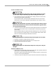
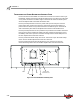
Figure 2-3: Power Distribution Assembly Fuses
F3, F4
F5
status light
F6
F1, F2
control panel
interface board