
Pest Control Equipment User Manual


CONTROL PANEL INTERFACE INSTALLATION
Routing Cables
Version 1 Control Panel Interface Installation and User Guide
1-25
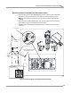
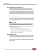
ROUTING THE PICKUP CARD AND DYNO ELECTRONICS CABLES
1 Route the pickup card cable (P/N 66953002) from the CPI through the designated
pit conduit and over to the pickup card. Attach the cable to the pickup card.
Note: Be sure to keep the power and communications cables in different pit
conduits.
2 Route the 25-pin cable (P/N 42924251) from the dyno electronics to the Breakout
board. Refer to Figure 1-1 for Breakout board location.
3 Route the 9-pin serial cable (P/N 42967090) from the dyno electronics to your
computer.
Figure 1-23: Route the Pickup Card and Dyno Electronics Cables
pickup card
dyno
electronics
CPI
25-pin cable to
breakout board
9-pin cable to
computer
pickup card cable
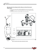
25-pin
cable to
breakout
board
route communications cables
in designated conduit