ASSEMBLY INSTRUC TIONS DX-WD1335 Wood TV Stand Tools needed........................................... 2 Parts ........................................................... 3 Hardware.................................................. 4 Assembly instructions .........................
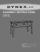
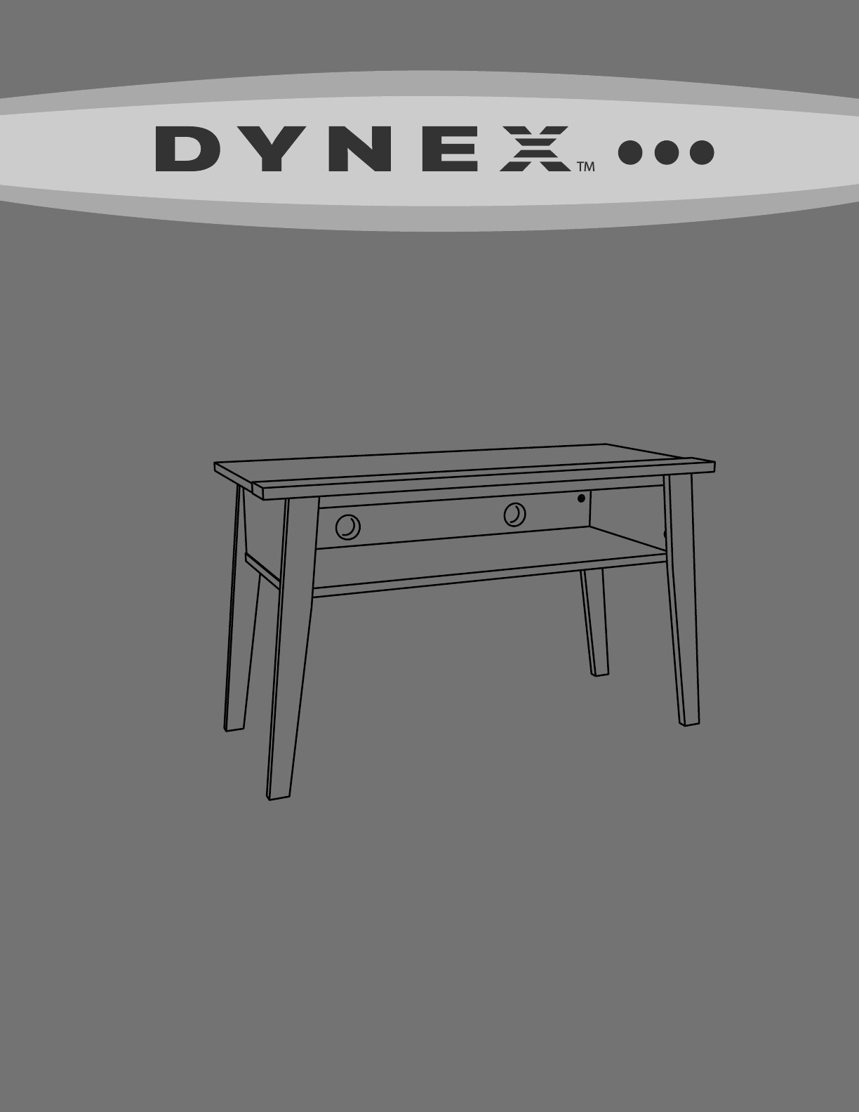
DX-WD1335 Safety information and specifications CAUTION: This stand’s wood surface is Weight capacity (top shelf): 50 lbs (22.7 kg) Weight capacity (lower shelf): 25 lbs (11.34 kg.) Overall dimensions (W × H × D): 36 × 21.75 × 15.75 in. (91.44 × 55.25 × 40 cm) Top shelf (W × D): 35.25 × 12.75 in. (89.54 × 32.39 cm) Usable lower shelf (W × H × D): 30.25 × 5.5 × 12.75 in. (76.84 × 13.97 × 32.39 cm) intended only for use with a product not weighing more than 50 lbs (22.
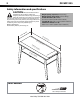
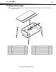
DX-WD1335 3 Parts Package contents: parts Note: Some parts have a label on the edge to help distinguish similar parts from each other. Use this illustration to help identify similar parts. Item Description Qty. Item Description Qty.
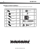
DX-WD1335 Hardware Package contents: hardware Make sure that you have all the hardware necessary to assemble your new TV stand: Label K L M Hardware Twist-lock® fastener Hidden cam Qty. Label Hardware 2 Q Cam cover 6 13 R Glue 1 6 Cam dowel S N Cam screw 7 O Angle bracket 2 P Wood dowel 20 Warning label T 11 Black 9/16" large head screw U 2 30 40 1 Black 1-7/8" flat head screw 2 1 10 Qty.
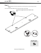
DX-WD1335 5 Assembly instructions Step 1: Caution: Assemble your TV stand on carpeted floor or on the empty carton to avoid scratching your stand or the floor. Push a Twist-lock® fastener (K) into each of the two the holes in the back (E). Important: Do not tighten the Twist-lock® fasteners in this step.
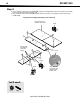
DX-WD1335 Step 2: 1 Push 13 hidden cams (L) into the ends (A and B), top (C), and back (E). Make sure that the arrows on the hidden cams (L) are pointing toward the closest edge. 2 Insert the metal end of a cam dowel (M) into each hidden cam, except in the top (C) and short edge of each end (A and B). Important: Do not tighten the hidden cams in this step. Do not insert cam dowels into this part. Arrow Do not insert cam dowels into these edges.
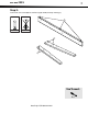
DX-WD1335 7 Step 3: Screw seven cam screws (N) into the front legs (F and G) and stop molding (J).
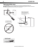
DX-WD1335 Tightening hidden cams: In the remaining steps, use these illustrations for instructions on tightening hidden cams. Warning: Risk of damage or injury. Hidden cams must be completely tightened. Hidden cams that are not completely tightened will loosen, and parts may separate. Arrow Make sure that you turn the hidden cam a minimum of 190° to a maximum of 210°. Note the position of the arrow on the hidden cam. Arrow 210° In the illustration below, the hidden cam has not been tightened enough.
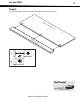
DX-WD1335 9 Step 4: Align the stop molding (J) with the top (C), then tighten the three hidden cams.
DX-WD1335 Step 5: Align the ends (A and B) with the back (E), then tighten the two hidden cams.
DX-WD1335 11 Step 6: Caution: Check the parts carefully before assembling. Disassembly of glued parts is extremely difficult. 1 Fill the holes in the stop molding (J) 1/4 to 1/2 full with glue (R), then insert the wood dowels (P) into the holes. Wipe away the excess glue. 2 Drop a few beads of glue (R) into the holes in the ends (A and B). 3 Align the ends (A and B) and the back (E) with the top (C) and the stop molding (J).
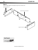
DX-WD1335 Step 7: 1 Attach two angle brackets (O) to the stop molding (J) using two black 9/16" large head screws (U). 2 Fasten the skirt (I) to the stop molding (J) using two black 9/16" large head screws (U). Note: There are no pre-drilled holes in the skirt. The screws tighten into the groove.
DX-WD1335 13 Step 8: 1 Align right front leg (F) with the right end (A) and the left front leg (G) with the left end (B), then tighten the four hidden cams (L). 2 Attach the rear legs (H) to the ends (A and B) using four black 1-7/8" flat head screws (T). Important: Make sure that the rear legs (H) angle out and away from the stand.
DX-WD1335 Step 9: Fasten the lower shelf (D) to the ends (A and B) and back (E) using seven black 1-7/8" flat head screws (T).
DX-WD1335 15 Step 10: 1 Carefully turn your TV stand upright. 2 Apply the warning label (S) to the top (C) so that the TV will hide the label. Peel off the backing and apply the label as shown in the diagram. Note: This is a permanent label intended to last for the life of the product. After you apply the label, do not try to remove it. 3 Push a cam cover (Q) onto each visible hidden cam. You’ll need: Q (6) For customer service, call: 800-305-2204 (U.S.
Certificate of Conformity 1. This certificate applies to the Sauder Woodworking Product identified by this instruction booklet. 2. This certificate applies to the compliance of this product with the CPSC Ban on Lead-Containing Paint (16 CFR 1303). 3. This product was manufactured by: Sauder Woodworking Company 502 Middle Street Archbold, Ohio 43502 (419) 446-2711 4. Date of Manufacture: _______________ Lot number: 345399 www.dynexproducts.