DX-DRTVM112_13-0668_MAN_V1_ENG.fm Page 1 Friday, July 19, 2013 10:37 AM A S S E M B LY G U I D E DX-DRTVM112 Low-Profile TV Wall Mount For either wood-stud or concrete wall installations Safety information and specifications . .2 Tools needed. . . . . . . . . . . . . . . . . . . . . . . . . .3 Package contents . . . . . . . . . . . . . . . . . . . . .4 Installation instructions. . . . . . . . . . . . . . . .5 Before using your new product, please read these instructions to prevent any damage.
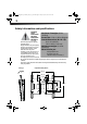
DX-DRTVM112_13-0668_MAN_V1_ENG.fm Page 2 Friday, July 19, 2013 10:37 AM 2 Safety information and specifications IMPORTANT SAFETY Maximum TV weight: 35 lbs. INSTRUCTIONS (15.8 kg) SAVE THESE INSTRUCTIONS Screen size: 13 in. to 36 in. diagonal CAUTION: Do Overall dimensions (H × W × D): not use this 9.5 x 2.5 x 9.25 in. product for any purpose not explicitly specified by Dynex. (24.1 × 6.35 × 23.5 cm) Improper installation may cause property Wall-mount weight: 2.115 lb. damage or personal injury.
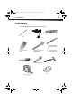
DX-DRTVM112_13-0668_MAN_V1_ENG.
DX-DRTVM112_13-0668_MAN_V1_ENG.
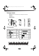
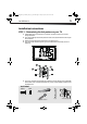
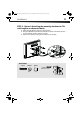
DX-DRTVM112_13-0668_MAN_V1_ENG.fm Page 5 Friday, July 19, 2013 10:37 AM 5 DX-DRTVM112 Installation instructions STEP 1 - Determining the hole pattern on your TV 1 Carefully place your TV screen face down on a cushioned, clean surface to protect the screen from damage and scratches. 2 If your TV has a table top stand attached, remove the stand. See the documentation that came with your TV for instructions. 3 Measure the distance between the mounting holes on the back of your TV.
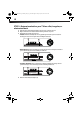
DX-DRTVM112_13-0668_MAN_V1_ENG.fm Page 6 Friday, July 19, 2013 10:37 AM 6 STEP 2 - Determine whether your TV has a flat, irregular, or obstructed back 1 Temporarily lay the TV bracket (A) and adapters (C), if necessary, on the back of your TV. 2 Align the screw holes in the TV bracket with the mounting screw holes on your TV. 3 Identify which type of back your TV may have: • Flat back: The bracket and adapters (if necessary) lay flush against the back of your TV and does not block any jacks.
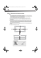
DX-DRTVM112_13-0668_MAN_V1_ENG.fm Page 7 Friday, July 19, 2013 10:37 AM 7 DX-DRTVM112 STEP 3 - Select screws and spacers 1 Select the hardware for your TV (screws and spacers). A limited number of TVs come with mounting hardware included. (If there are screws that came with the TV, they are almost always in the holes on the back of the TV.) Select one of the following types of screws: M4 × 12 mm screws (E) for a flat back TV. M4 × 35 mm screws (F) for an irregular or obstructed TV back.
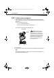
DX-DRTVM112_13-0668_MAN_V1_ENG.fm Page 8 Friday, July 19, 2013 10:37 AM 8 STEP 4 - Option 1: Attaching the mounting hardware to TVs with a flat back 1 Align the TV bracket (A) with the screw holes on the back of the TV. 2 Install washers (G ), and screws (E) into the holes in the back of the TV. 3 Tighten the screws until they are snug against the TV bracket. Do not over tighten.
DX-DRTVM112_13-0668_MAN_V1_ENG.fm Page 9 Friday, July 19, 2013 10:37 AM 9 DX-DRTVM112 STEP 4 - Option 2: Attaching the mounting hardware to TVs with irregular or obstructed backs 1 Align the TV bracket (A) with the screw holes on the back of the TV. 2 Place spacers (H) behind the TV bracket and the washers (G) over the holes in the TV bracket, then insert the screws (F) through the washers, TV bracket, and spacers. 3 Tighten the screws until they are snug against the TV bracket. Do not over tighten.
DX-DRTVM112_13-0668_MAN_V1_ENG.fm Page 10 Friday, July 19, 2013 10:37 AM 10 STEP 5 - Determine wall-mount location Notes: • For more detailed information on determining where to drill your holes, visit our online height-finder at: http://mf1.bestbuy.selectionassistant.com/index.php/heightfinder • Your TV should be high enough so your eyes are level with the middle of the screen. Normally, the center of your TV should be 40 to 60 inches (100 to 150 cm) above the floor.
DX-DRTVM112_13-0668_MAN_V1_ENG.fm Page 11 Friday, July 19, 2013 10:37 AM 11 DX-DRTVM112 STEP 6 - Option 1: Installing on a wood stud* wall Note: Any drywall covering the wall must not exceed 5/8" (16 mm). 1 Locate the stud. Verify the center of the stud with an edge-to-edge stud finder. 2 Align the wall plate template (D) at the height you determined in the previous step and make sure that it is level. Tape the wall plate template in position, then use a pencil to mark the lag bolt hole locations (2).
DX-DRTVM112_13-0668_MAN_V1_ENG.fm Page 12 Friday, July 19, 2013 10:37 AM 12 STEP 6 - Option 2: Installing on a solid concrete* or concrete block wall CAUTION: To prevent property damage or personal injury, never drill into mortar between 1 2 3 4 blocks. Mount the wall plate directly onto the concrete surface. Align the wall plate template (D) at the height you determined in the previous step and make sure that it is level.
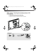
DX-DRTVM112_13-0668_MAN_V1_ENG.fm Page 13 Friday, July 19, 2013 10:37 AM 13 DX-DRTVM112 STEP 7 - Mounting the TV to the wall plate 1 Place the TV bracket (A) into the slotted flanges of the wall plate (B). The TV can be mounted either (1) vertically, or (2) with a 6° tilt. 2 Lock the TV and bracket assembly to the wall plate by rotating the lock into the flange slot. HEAVY! You will need assistance with this step.
DX-DRTVM112_13-0668_MAN_V1_ENG.fm Page 14 Friday, July 19, 2013 10:37 AM 14 STEP 8 - Removing the TV from the wall plate and disassembling the wall mount 1 Unlock the TV and bracket assembly from the wall plate by rotating the lock out of the flange slot. 2 Lift the TV bracket (A) from the slotted flanges of the wall plate (B) and place it on a cushioned, clean surface to protect the screen from damage and scratches.
DX-DRTVM112_13-0668_MAN_V1_ENG.fm Page 16 Friday, July 19, 2013 10:37 AM www.dynexproducts.com 1-800-305-2204 (U.S. and Canada) or 01-800-926-3020 (Mexico) Distributed by Best Buy Purchasing, LLC 7601 Penn Ave. South, Richfield, MN 55423 U.S.A. © 2013 BBY Solutions, Inc. All rights reserved. DYNEX is a trademark of BBY Solutions, Inc. Registered in some countries. All other products and brand names are trademarks of their respective owners.