
Product specifications
Diamond 36kW Manual Dynatronix, Inc.
198-1600-00 Rev F Page 75 of 146
14. The lower current control analog input calibration value (CL11) is automatically updated
to reflect the connected calibrator output. Wait a few seconds for the calibration value
to stabilize and then press the voltage encoder switch to accept the new value and
return to the “Option Card Calibration Menu”.
15. From the “Option Card Calibration Menu” rotate the current encoder until the display
shows “CAL” “CL12”. Press the voltage encoder switch to view and change the lower
current read back analog output calibration point. The top display will show “I.Lo rEAd
CL12”, the bottom display shows the calibration point value.
16. Put the supply in REMOTE mode (press the RMT/LCL switch so that the RMT/LCL
lamp is on) to begin calibrating the lower current read back analog output calibration
point.
17. Adjust the current encoder until the calibrator input reads the proper value for 10% of
the analog output control signal (5.6mA for 4-20mA or 0.5V for 0-5V or 1V for 0-10V).
18. Press the voltage encoder switch to accept the new calibration value and return to the
“Option Card Calibration Menu”.
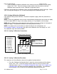
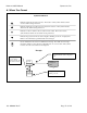
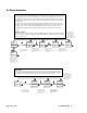
19. Connect the calibrator (Ronan model x86 or equiv.) to the Analog Control connector of
the power supply as shown above for the voltage calibration connections (connect the
calibrator output to the power supply analog voltage control input, connect the calibrator
input to the power supply analog voltage read back output). The calibrator should be set
to a range that will maximize resolution (20mA for a 4-20mA interface,5v for 0-5v
interface, or 10v for 0-10v interface).
20. From the “Option Card Calibration Menu” rotate the current encoder until the display
shows “CAL” “CL13”. Press the voltage encoder switch to view and change the upper
voltage control analog input calibration point. The top display will show “E.Hi CtL
CL13”, the bottom display shows the calibration point value.
21. Set the calibrator output to 20mA (5V for 0-5V or 10V for 0-10V).
22. Put the supply in REMOTE mode (press the RMT/LCL switch so that the RMT/LCL
lamp is on) to begin calibrating the upper voltage control analog input calibration point.
23. The upper voltage control analog input calibration value (CL13) is automatically updated
to reflect the connected calibrator output. Wait a few seconds for the calibration value
to stabilize and then press the voltage encoder switch to accept the new value and
return to the “Option Card Calibration Menu”.
24. From the “Option Card Calibration Menu” rotate the current encoder until the display
shows “CAL” “CL14”. Press the voltage encoder switch to view and change the upper
voltage read back analog output calibration point. The top display will show “E.Hi rEAd
CL14”, the bottom display shows the calibration point value.
25. Put the supply in REMOTE mode (press the RMT/LCL switch so that the RMT/LCL
lamp is on) to begin calibrating the upper voltage read back analog output calibration
point.
26. Adjust the current encoder until the calibrator input reads the proper value for 100% of
the analog output control signal (20mA for 4-20mA or 5V for 0-5V or 10V for 0-10V).
27. Press the voltage encoder switch to accept the new calibration value and return to the
“Option Card Calibration Menu”.