
Product specifications


Diamond 36kW Manual Dynatronix, Inc.
198-1600-00 Rev F Page 67 of 146
Voltage Calibration Load: The current developed across the load should be 375 amps at
24 volts. To determine the load resistance value use Ohms law:
24 Volts / 375 Amps = 0.064 ohms
To determine the wattage use:
24 volts x 375 amps = 9000 watts
To calibrate the voltage settings it will be necessary to connect a load with a resistance
value of 0.064 ohms and 18000 watts (twice calculated wattage).
10.1.2. Calibration Summary
NOTE: Each 18kW module must be individually calibrated.
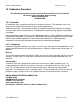
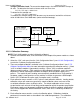
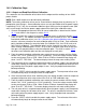
1. Connect the calibration load, shunt and meters to the output of the power module as shown
above.
2. Select the “CAL” sub menu from the “Unit Configuration Menu” (see 6.3.Unit Configuration)
to enter the “Calibrate Configuration Menu”.
3. There are multiple calibrations available in the “Calibrate Configuration Menu” (see A.7.5:
Calibrate Configuration Menu for more information regarding the calibration menus). Select
“rd A” to calibrate module A (top module) readings. Select “rd b” to calibrate module B
(bottom module) readings. Each module must be calibrated individually, even if the module
output buses will be connected to combine the outputs when the power supply runs a
process. The module A and B reading are automatically combined into a single reading if
the power supply is configured to use the modules in tandem to generate a 36kW output.
Select “OPt” to calibrate the option card (if an option card is installed).
4. Each calibration menu contains a “dFLt” option to load calibration defaults. Loading default
calibration values will remove any previously stored calibration values and reset all the
associated calibration values to default values. The default calibration values are not
customized to each unit and will not likely provide operation within the product specification.
Each power supply must be properly calibrated to operate within the product specifications.
Units are not shipped with default calibration values, each unit is individually calibrated at
the factory.
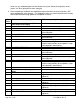
5. Each calibration menu contains a series of calibration points. Calibration should be
performed in numerical order as described in the calibration procedure. The calibration
4.5 DIGIT DVM
(VOLTAGE)
4.5 DIGIT DVM
(CURRENT)
POSITIVE
OUTPUT
NEGATIVE
OUTPUT
POWER SUPPLY
SHUNT
LOAD
18kW Module
18kW Module
NOTE: Only connect the
calibration load to the module
being calibrated.