
Product specifications


Page 144 of 146 198-1600-00 Rev F
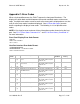
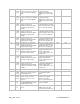
94
Output
Channel
(0 to n)
A complete shut down occurred
during operate mode. Power was
lost and the output was disabled.
This fault is only flagged as an
active fault if power fail faults are
enabled in the unit configuration
menu.
This fault must be manually
cleared.
NO
YES
95
Output
Channel
(0 to n)
Primary power was lost during
operate mode and the power
supply output was disabled. This
fault can occur if primary input is
temporaritly lost and then returns
before a complete shut down
occurs. This fault is only flagged
as an active fault if power fail
faults are enabled in the unit
configuration menu.
This fault must be manually
cleared.
NO
YES
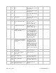
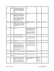
96
System
(0)
A waveform file could not be
written to memory or could not be
read from memory. The error can
be caused by a failure to write
memory properly or by an invalid
waveform file.
This fault can be manually
cleared.
NO
YES
97
System
(0)
Communications failure with the
display.
This fault self clears when
display communications resume.
The fault can also be manually
cleared allowing the power
supply to operate again, if the
operate state is controlled by a
source other than the display
(digital input or host port).
YES
YES
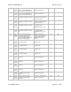
98
System
(0)
The display communications port
(U3) could not be initialized.
Cycle power
NO
YES
99
System
(0)
Display communications port
software FIFO overflow (U3)
This fault is logged to fault
history for diagnostics purposes,
it is not flagged as an active
fault.
NO
YES
100
System
(0)
Display communications framing
error (U3)
Diagnostics purposes only, not
set in production software.
N/A
N/A
101
System
(0)
Host port communications watch
dog timer (WDT) timeout. This
fault occurs when the host port
WDT timeout period (host port
configuration menu) is set to a
non-zero value and valid serial
communications have not been
received on the host port for the
WDT timeout period.
This fault auto clears when valid
host port communications are
received or the host port WDT
timeout period is changed to
zero.
YES
YES
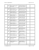
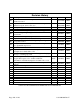
102
Inveter
Control
(0 to n)
Module A temperature sensor
value out of range (short or open)
Replace the sensor or fix
broken/shorted connections.
YES
YES
103
Inveter
Control
(0 to n)
Module B temperature sensor
value out of range (short or open)
Replace the sensor or fix
broken/shorted connections.
YES
YES
104
System
(0)
Inverter synchronization error.
Synchronization is required to
align waveform outputs for all
inverters connected to the same
output. The digital sync signal
either was lost completely or one
or more transitions were missed.
The fault must be manually
cleared. The fault will re-occur if
the synchronization errors
continue.
Output is
disabled
on any
inveter
reporting a
sync fault.
YES