
Product specifications


Diamond 36kW Manual Dynatronix, Inc.
198-1600-00 Rev F Page 131 of 146
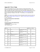
B.1.19 Unit Settings Command “t”:
@AA.a
Sync character (@) and unit address, AA = Unit ID (0 to 99; 0 is a global ID), a (n/a,
set to zero)
t0
Command character and Type – 0=read, 1=set, 2=activate(n/a), 3=ack, 4=nak
#16,
Number of fields character and number of fields after the comma, excluding CRC
0,
Control Type 0=Panel, 1=Host, 2=Analog/Panel, 3=Analog/Host
ctl
1,
unit address – 1 to 99, (unit address used in the header of each command)
addr
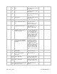
0,
Host port baud rate – 0 = 9600 (default), 1 = 19200, 2 = 38400, 3 = 57600, 4 =
115200
bps
0,
Power Up Mode – 0 = always start in standby, 1 = return to last state
pwr
0,
Power Fail Error Enable - 1 = enable power failure errors, 0 = disable power failure
errors (when disabled the error codes are still logged to the error history log, but they
are not displayed on the front panel or reported to the host in the “m” alarm status
message). There is a separate error code for a brief power failure (error code 103)
that did not cause a complete power loss but did disable the output, and a complete
power loss (error code 102).
pf
0,
Front panel operate switch enable (0 = locked, 1 = enabled) (pots and meters display
only)
opsw
0,
Front panel remote switch enable (0 = locked, 1 = enabled) (pots and meters display
only)
rmsw
0,
Clear Active Errors ( 0 = no action, A numeric value clears the associated error code,
32767 clears all active error codes). If the error conditions still exists after an error
code is cleared the error code will be set again. The action of setting this parameter
to a non-zero number clears the associated alarm, the value of this parameter is not
stored and will always be read as zero.
eclr
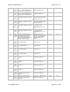
0,
Digital Input Configuration: 0 = Disabled, 1 = Operate On Close, 2 = 1 Push For
Operate, 3 = 2 Push for Operate, 4 = Operate On Close and inhibit on open (operate
not allowed if contact is open, see "on 3" in the user manual). For complete
descriptions of each Digital input configuration see the user manual.
dst
0,
Front Panel Run Screen Select: 0 = meters, 1 = totalizer status, 2 = cycle status, 3 =
expectd average current in current regulation mode CH1, 4 = expectd average voltage
in voltage regulation mode CH1, 5 = expectd average current in current regulation
mode CH2, 6 = expectd average voltage in voltage regulation mode CH2 (screens 3
to 6 are diagnostic screens) (only used for the pots and meters display)
scr
0,
Front Panel Error Message Disable – 1 = Disable display of error codes on the front
panel, 0 = enable display of error codes on the front panel (the fault lamp is active
regardless of this setting, if the error messages are disabled (0) then the fault lamp
will flash on and off when a new error code is set). This setting is not retained through
a power cycle and defaults to 0 at power up. (only used for the pots and meters
display)
edis
0,
Front Panel Unit Configuration Password (code) – 0 to 9999. This is the code that
needs to be entered from the front panel to access the unit configuration menu. If the
code is known it can also be changed from the front panel within the unit configuration
menu. The default code from the factory is 0000. This serial command does not
require the existing code to be known, it is the responsibility of host application to
protect this password and keep in hidden if desired.
pswd
0,
Host port watch dog timer (WDT) time out. 0 to 65.535 seconds. A value of zero
wdt