
Product specifications

Diamond 36kW Manual Dynatronix, Inc.
198-1600-00 Rev F Page 129 of 146
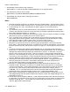
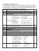
2. This is a variable length message, dependent on the number of alarms in the alarm status buffer.
3. Use the table of alarms to determine what each alarm code means.
4. The channel ID ‘a’ should always be zero.
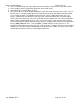
5. The error number is a 16 bit integer containing a 12 bit error code and a 4 bit error source. The 12
bit error code is a unique number that can be looked up in the error code table to determine what
issue is being reported. The definition of the 4 bit error source is dependent on the error. For
process related errors (like tolerance errors) the error source will indicate the associated output
channel that caused the error. For errors related to inverter hardware the error source will indicate
which inverter control flagged the error. If the error source value is zero, then the error number is
not associated with a specific output channel or inverter. Example: Error number 4187 translated to
binary is 0001 0000 0101 1011. The four MSBits (in bold) indicate an error source of 1. The
remaining 12 bits indicate an error code of 91. Error code 91 is a voltage tolerance error, the output
voltage is less than the voltage setting by more than the tolerance setting. The error source value
of one indicates that this error was set by output channel one.