
Product specifications


Page 126 of 146 198-1600-00 Rev F
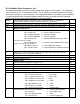
B.1.16 Module Status Command “ms”:
This command provides specific information about each power inverter module. This command is
not a substitute for the “d” readings command. The “d” readings command provides true voltage
and current readings as seen by the load. The reading information in the module status command
is reading information for the specified power module and may not reflect the actual current or
voltage seen by the external load (depending on the configuration).
@AA.a
Sync character (@) and unit address, AA = Unit ID (0 to 99; 0 is a global ID), a
(power module number, 1 to the number of modules in the system)
ms0
Command character and Type – 0=read, 1=set(n/a), 2=activate(n/a), 3=ack, 4=nak
#15,
Number of fields character and number of fields after the comma, excluding CRC
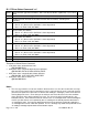
Module Readback Info
3,
Supply Status { Bit 0: Inverter Ready ‘1’ = Ready to regulate
Bit 1: Primary OK ‘1’ = Primary voltage is present
Bit 2: Voltage Regulation ‘1’ = Voltage regulation
Bit 3: Current Regulation ‘1’ = Current regulation
Bit 4: Critical Fault ‘1’ = output disabled (see the alarm status
message for a list of faults)
Bit 5: General Fault ‘1’ = operate may be limited (see the alarm
status message for a list of faults)
Bit 6: Boost Time out ‘1’ = PFC PWM switch timeout
Bit 7: Interlock Active ‘1’ = Output disabled by hardware interlock
}
ss
0,
Active Link { The link or internal ramping step that was active when the read back
information in this message was collected}
lnk
120.5,
Average Current { Amps }
afi
15.75,
Average Voltage {Volts }
afv
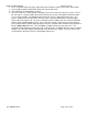
Module Status
35,
Primary Heatsink Temperature {degrees C}
pht
45,
Secondary Heatsink Temperature {degrees C}
sht
240,
Primary Voltage {RMS Volts AC}
pv
448,
Top Bus Voltage {Peak voltage}
tbv
449,
Bottom Bus Voltage {Peak voltage}
bbv
0,
Module Status 1 { Bit 0: Interlock active ‘1’ = Interlock active
Bit 1: Inverter Primary OT ‘1’ = Over Temp
Bit 2: Inverter Secondary OT ‘1’ = Over Temp
Bit 3: XFMR #1 Current Fault ‘1’ = Fault
Bit 4: XFMR #2 Current Fault ‘1’ = Fault
Bit 5: Bus Balance Fault ‘1’ = Fault
Bit 6: Primary Connection ‘1’ = Fault
Bit 7: Single Phase Primary ‘1’ = Single Phase }
ms1
2,
Module Status 2 { Bit 0: Line Limit Foldback ‘1’ = inverter output reduced
Bit 1: Bus OK ‘1’ = bus voltage ready
Bit 2: Configuration fault ‘1’ = Fault
Bit 3: Primary OK ‘1’ = Primary Voltage OK
ms2