
Product specifications


Page 18 of 150 198-1603-03 Rev 01
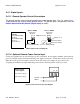
5.4.2. Digital Outputs
5.4.2.1. End Of Cycle Status Connections
Digital output pins 1(+) and 2(-) can be used to sense when the end of a timed cycle (ATC or
RTC) has been reached. The output will switch on to indicate the end of a cycle. If the power
supply contains more than one output channel the output is activated when any of the output
channels has reached the end of a cycle, there is not a separate output for each channel. For
remote sense of the end of cycle for individual output channels the serial host port interface
should be used.
5.4.2.2. Alarm/Fault Status Connections
Digital output pins 3(+) and 4(-) can be used to sense the presence of one or more alarm
conditions. When one or more alarms are active (the remote control fault lamp will also be on) the
alarm output is switched on. To remotely detect the presence of specific alarms or fault conditions
use the serial host port interface. The details of what each alarm code indicates and how it can be
cleared can be found in Appendix C: Error Codes.
5.4.2.3. Operate Status Connections
Digital output pins 5(+) and 6(-) can be used to sense when the power supply is operating. The
output will switch on when the power supply is operating. If the power supply contains more than
one output channel the output is switched on when any of the output channels is operating. For
remote sense of the operate state for individual output channels the serial host port interface
should be used.