
Product specifications


Page 16 of 150 198-1603-03 Rev 01
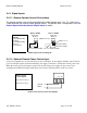
5.4. Digital I/O
The 12 pin connector on the back panel contains all of the digital inputs and outputs.
The digital operate input can be wired for operate on close or operate on open switch contacts.
See the diagram in 5.4.1.1 Remote Operate Control Connections for details.
The digital input for the power relay requires a 24V signal be attached in order for the power
supply to be operational.
A series of digital outputs are available to provide status information for process control. Each
output is an open collector output. The output should be used to switch no more than 24VDC and
no more than 35mA. Polarity of the connections should be observed. It is the customer’s
responsibility to ensure any circuit connected to the digital outputs meets the above criteria.
Failure to stay within the specified maximum ratings will result in damage to the digital outputs.
1 - (+) End Of Cycle Output
2 - (-) End Of Cycle Output
3 – (+) Alarm Output
4 – (-) Alarm Output
5 – (+) Operate Status Output
6 – (-) Operate Status Output
7 – Inhibit/Stby on Open (in)
8 – Inhibit/Stby on Close (in)
9 – Common
10 – N/C
11 – (+) Power Relay Input
12 – (-)Power Relay Input
+
-
Digital I/O Signals
Typical Output Circuit
Remote Control Connector
(alarm output shown)
Customer Circuit
Max Voltage: 24V
Max Current: 35mA
V+
V-
R= Current limiting resistor
3
4