Dynatron 900+™ CAUTION: Federal law restricts this device to sale by or on the order of a physician, chiropractor, physical therapist, or dentist, licensed by the law of the state in which said person practices, to use or order the use of the device. IMPORTANT: Traction Therapy must be prescribed by a licensed practitioner following an appropriate physical examination and diagnostic analysis.
Dynatron 900+™ TABLE OF CONTENTS SECTION I INTRODUCTION .................................................................................................................. 1 BEFORE YOU TREAT A PATIENT ..................................................................................................................... 1 INSTALLATION AND FEATURES ...................................................................................................................... 2 UNPACKING...................................
Dynatron 900+™ iv
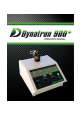
Dynatron 900+™ SECTION I INTRODUCTION The Dynatron 900+ Traction system is intended for medical purposes for use in conjunction with traction accessories such as belts and harnesses to exert therapeutic pulling forces on the patient’s body primarily for the cervical and lumbar areas. The Dynatron 900+ manual contains operating instructions for the Dynatron 900+ Microprocessor-controlled Traction system. A copy of this manual should be left with the device at all times.
Dynatron 900+™ INSTALLATION AND FEATURES UNPACKING When you receive the unit, immediately unpack it as well as all accessories and check for possible damage, obvious or concealed. In case of damage, immediately notify the freight carrier and take any steps necessary to file a claim for the damage sustained. Do not destroy or discard the shipping carton. The carton should be reused if the device must be shipped for any reason. The carton is specially designed to protect the unit from shipping damage.
Dynatron 900+™ SECTION II PHYSICAL FEATURES Before operating the Dynatron 900+, acquaint yourself with the physical and operational aspects of the device by reviewing the instructions and illustrations within this manual. The numbered features in the diagrams located at the end of this section correspond to the numbered descriptions on the following pages.
Dynatron 900+™ DESCRIPTION OF PHYSICAL FEATURES 1. ON/OFF TOGGLE SWITCH The On/Off Toggle Switch is located on the left-side of the lower front panel. When the toggle switch is in the “1” (on) position, the LED above the Reset Key is illuminated green as well as other display windows and indicators on the device faceplate. 2. TIME SELECTOR ARROWS Located in the upper right-hand corner of the faceplate, these Time Selector Arrow Keys are used to set the treatment time within a range of 1-99 minutes.
Dynatron 900+™ DYNATRON 900+ NUMBERED FEATURES 5
Dynatron 900+™ 11. HOLD FORCE CONTROL KNOB Hold Force is set by using the circular knob located on the right-hand side of the device. There are three numbered circles surrounding the knob. The inside circle indicates force in Newtons, the middle circle indicates kilograms, while the outside circle indicates force in pounds. Force is selected by aligning the gray dot on top of the knob with the desired Newtons/ kilograms/pounds of force desired. Hold Force ranges from 4 – 200 lb; 2 – 91 kg; or 20 – 890N.
Dynatron 900+™ 18. MAX FORCE LEDS Under the Max Force heading, three maximum force selections are listed. Selection is made by holding down the “Rest” Key while pressing the SP Key. The LED next to each Max Force selection becomes illuminated when the selection is active. 890N / 91kg / 200lb 490N / 50kg / 110lb 180N / 18kg / 40lb 19. SPEED CONTROL KNOB This knob labeled “Speed” controls the variable "Pull" and "Release" speed of the rope.
Dynatron 900+™ SECTION III OPERATING INSTRUCTIONS This section contains detailed procedures for the operation of the Dynatron 900+ Traction Unit. These procedures are designed to familiarize the user with the operation and function of the device. Read this section thoroughly along with all contraindications, warnings, and precautions before operating this device. WARNING • Thoracic, Pelvic and Cervical harnesses must be securely in place before traction treatment begins.
Dynatron 900+™ DETAILED TREATMENT SETUP 1. According to manufactures’ instructions, prepare the patient for treatment. Make sure all belts and harnesses are securely attached. 2. The Remote Stop cable must be plugged into the console before the device is turned “on.” Connect the Remote Stop plug to the Remote Jack located in the center of the rear panel and hand the Remote Stop switch to the patient. 3. Turn the Power Switch to “1” (on).
Dynatron 900+™ 11. At the end of a treatment, the 900+ unit will beep (unless muted). The LED above the Rest key will flash, the Treatment Time Display Window will flash “00” and the tension on the rope will ramp down to 4 lbs. Press the Reset Key to conclude the treatment and release all tension from the rope. The 900+ is now ready for program changes or to setup a new treatment.
Dynatron 900+™ ADDITIONAL TRACTION MODES – QUICK SETUP INSTRUCTIONS STATIC INSTRUCTIONS 1. Prepare the patient for the traction treatment. Make sure all belts and harnesses are securely attached. 2. Plug in the remote stop cable and hand it to the patient. 3. Turn on the Dynatron 900+ device. 4. Set Treatment Time: 1-99 min. 5. Set Hold Force Timer: “- -” sec. 6. Set Hold Force: 2 - 91 kg. or 4 – 200 lbs. 7. Adjust Speed Fast 8. Press Start Static Cycle INTERMITTENT INSTRUCTIONS 1.
Dynatron 900+™ STEPLESS PROGRESSIVE 1. Prepare the patient for the traction treatment. Make sure all belts and harnesses are securely attached. 2. Plug in the remote stop cable and hand it to the patient. 3. Turn on the Dynatron 900+ device. 4. Set Treatment Time: 1-99 min. 5. Set Hold Force Timer: 1-99 sec. 11. Set Rest Force Timer: 1-99 sec. 12. Set Hold Force: 4 – 200 lbs. or 2 - 91 kg. 13. Set Rest Force: 0 – 197 lbs. or 0 - 90 kg. Must be set lower than Hold Force value. Intermittent Cycle 14.
Dynatron 900+™ SECTION IV CONTRAINDICATIONS, WARNINGS, AND PRECAUTIONS RELATED TO MECHANICAL SPINAL DECOMPRESSION Traction Therapy must be prescribed by a licensed practitioner following an appropriate physical examination and diagnostic analysis. The Dynatron 900+ Traction system is intended for medical purposes for use in conjunction with traction accessories such as belts and harnesses to exert therapeutic pulling forces on the patient’s body primarily for the cervical and lumbar areas.
Dynatron 900+™ SECTION V TECHNICAL INFORMATION SUGGESTED MAINTENANCE SCHEDULE SERVICE TO BE PERFORMED BY A TECHNICIAN ANNUAL CALIBRATION It is recommended that the Dynatron 900+ device be sent to the manufacturer for annual calibration. MAINTENANCE PERFORMED BY USER 1. Inspect the Dynatron 900+ ropes/cables and connectors daily for wear and damage. Replace accessories as needed. 2.
Dynatron 900+™ RETURNING A UNIT FOR REPAIR If it becomes necessary to return the Dynatron 900+ for repair, contact your Dynatronics’ Dealer for assistance. If unable to contact your Dynatronics’ Dealer, call Dynatronics’ Customer Service (800) 874-6251. The following information must be supplied when calling Dynatronics’ Customer Service to obtain a return Service Order Number (SVO): 1. 2. 3. 4.
Dynatron 900+™ SECTION VI ASSEMBLY AND MAINTENANCE PULLEY HEAD Whenever the Pulley Head is replaced or removed from the device, turn the pulley head to the left until the breach points are aligned and the pulley easily slips from the enclosure. Do not force. REMOVING THE CHASSIS 1. Remove the two screws from the back panel of the chassis (A). 2. Remove the bottom plate and side panels will fall free.
Dynatron 900+™ DYNATRON 900+ WALL INSTALLATION 1. Align 2 special mounting screws in screw holes (D). 2. Align with device with the mounting bracket. 3. Attach the device with hand-screws (E). DYNATRON 900+ PLATFORM INSTALLATION 1. Align hole A on the machine with pin F on the installation plate. 2. Turn the machine to the desired orientation. 3. Tighten the 4 hand-screws ( E). DYNATRON 900+ TABLE INSTALLATION 1. Tighten stud to two screw holes (G). 2. Attach universal mounting bracket to stud. 3.
Dynatron 900+™ MACHINED HOLE SIZES A. Alignment hole 3/8” dia. B. Alignment set pin holes ¼” dia. C. Screw-holes for table mount & wall mount 5/16”-18UNC D. Knob for wall bracket 5/16”-18UNC E.
Dynatron 900+™ HOW TO REPLACE THE TRACTION CABLE Traction cable should be non-conductive. Minimum cable strength 700 lbs. (320kgs/ 3200N). 1. Loosen the screw E. (Fig 1) 2. Pass the cable around pulley A. (Fig 1) 3. Thread the cable through the hole of pulley B, go around the main shaft and under cable; pull cable tight to secure the end of cable against the main shaft. (Fig 1) Fig 1 Fig 5 4. Pass side P2 of cable to pulley C. (Fig 2) 5. Then pass pulley D. (Fig 3) 6. Go around head pulley.
Dynatron 900+™ HOW TO REPLACE FUSES Fuse 250V / 1.6A (100-120V) STEP 5: Turning clockwise, use a screwdriver to reattach the fuse cover. STEP 1: Turning counter clockwise, use a screwdriver to remove the fuse case cover. FUSE 250V / 0.8A (220-240V) STEP 2: STEP 1: Remove the fuse and fuse case. Turning counter clockwise, use a screwdriver to remove the fuse case cover. STEP 3: STEP 2: Remove the used fuse from the fuse case. Insert the new fuse. Remove the fuse and fuse case.
Dynatron 900+™ DEFINITION OF SYMBOLS AND LABELING Some or all of the following symbols are included in the labeling for this device. Definitions accompany each symbol. Please read the Operations Manual Carefully before using this device.
Dynatron 900+™ ELECTROMAGNETIC EMISSIONS AND IMMUNITY Tables 1 through 4 below list the Dynatron 900+ declarations of electromagnetic emissions and immunity, and give user guidance on the Dynatron 900+ in an electromagnetic environment per IEC 60601-1-2 guidelines. Table 1 Guidance and Manufacturer's Declaration - Electromagnetic Emissions The Dynatron 900+ (and accessories) is intended for use in the electromagnetic environment specified below.
Dynatron 900+™ Table 2 Guidance and Manufacturer's Declaration - Electromagnetic Immunity The Dynatron 900+ (and accessories) is intended for use in the electromagnetic environment specified below. The customer or the user of the Dynatron 900+ (and accessories) should assure that it is used in such an environment.
Dynatron 900+™ Table 3 Guidance and Manufacturer's Declaration - Electromagnetic Immunity The Dynatron 900+ (and accessories) is intended for use in the electromagnetic environment specified below. The customer or the user of the Dynatron 900+ (and accessories) should assure that it is used in such an environment.
Dynatron 900+™ Table 4 Recommended separation distance between portable and mobile RF communications equipment and the Dynatron 900+ (and accessories) The Dynatron 900+ (and accessories) is intended for use in an electromagnetic environment in which radiated RF disturbances are controlled.
Dynatron 900+™ DYNATRON 900+™ LIMITED WARRANTY Dynatronics CORPORATION warrants the Dynatron 900+, to be free from factory defects in materials and workmanship under normal use for ONE YEAR from the date of purchase by the original owner.
Dynatron 900+™ 27
Dynatron 900+™ DYNATRONICS 900+™ WARRANTY REGISTRATION TO REGISTER THE WARRANTY FOR YOUR DYNATRONICS UNIT, REMOVE THIS SELF-MAILER PAGE, COMPLETE ALL INFORMATION REQUESTED, AND MAIL TO DYNATRONICS.