
Product Manual

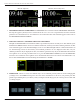


DYNATRON® 25 SERIES PHYSICAL FEATURES
DYNATRON® 25 SERIES™ | OPERATOR’S MANUAL 13
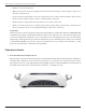
14. Le-Side Panel Jacks
SD Card Input. Located on the le-side of the 25 Series devices is the SD Card Input. e SD Input provides a way
for the 25 Series Devices to receive soware updates quickly and easily. Complete instructions for updating the
devices using an SD card are found in the “Technical” information section of the manual.
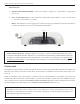
15. Right-Side Panel Jacks
Located on the right-side of the 25 Series are the Ultrasound, Combo Stim Probe Jacks. Non-ultrasound devices
(525 and 625) have no input jacks on the right-side panel.
Input (ElectroStim Combo Jack).
e special combo lead wire for combination treatments is plugged into this jack for a combination treatment setup
providing Stim output through the Ultrasound head. e Combination Treatment (Combo) Jack is a simple banana
jack connector and requires no special alignment.
Ultrasound Jack.
e Ultrasound Jack is a keyed jack with a “D” shaped conguration. Align the straight bottom of the jack and the
round top that matches the conguration found on the Ultrasound cord. Do not force or twist the connector or
damage to the pins may occur. When removing the connector, pull the connector’s outer sleeve directly away from
the chassis. When an Ultrasound probe is connected, the device console will update the probe calibration data. No
user inputs will be required to update calibration data.
Le-Side Panel Jacks
Right-Side Panel Jacks