DYNATRON® 25 SERIES™ | OPERATOR’S MANUAL I
CAUTION Federal law restricts these devices for sale by or on the order of a physician, chiropractor, physical therapist, or dentist licensed by the law of the state in which said person practices to use or order the use of the devices. Risk of burns and fire - Do not use near conductive materials such as metal bed parts, inner spring mattresses and the like. DANGER - Explosion Hazard: Do not use in the presence of flammable anesthetics.
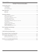
Table of Contents Table of Contents Section I: Introduction Introduction to the Dynatron® 25 Series™.............................................................................................. 1 Summary of Features by Device................................................................................................................................................1 Simplified Setup...........................................................................................................................
Table of Contents Section II: Operation and Treatment Instructions Interferential / Premodulated Instructions.......................................................................................... 25 Detailed Interferential / Premodulated Setup.......................................................................................................................25 Interferential and Premodulated Modality Information......................................................................
Table of Contents Ultrasound Modality Information........................................................................................................ 53 Selecting the Appropriate Soundhead....................................................................................................................................53 Penetration of Ultrasound Waves...........................................................................................................................................
Table of Contents Section IV: Technical Information Technical Information.......................................................................................................................... 76 Setting Defaults.........................................................................................................................................................................76 Save New Defaults..........................................................................................................
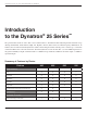
Introduction to the Dynatron® 25 Series™ Introduction to the Dynatron® 25 Series™ The powerful and versitle 25 Series offers 3 and 5 channel devices. All channels allow fully-independent treatment setups offering Interferential, Premodulated, High Volt, Biphasic, Russian, Microcurent, and fixed frequency IFC/Premod. In addition, the 925 and 825 include Dynatronics’ Ultrasound Comboplus feature with the power to deliver up to 5 channels of Stim and Ultrasound - all at the same time.
Introduction to the Dynatron® 25 Series™ Feature 925 825 625 525 High Volt Channel 1 1 1 1 Ultrasound Channel 1 1 Combo Channel 1 1 The 25 Series devices include the standard advantages of Dynatronics engineering, such as customizable treatments, electrode conductance meters, and the popular Target feature. In addition all units offer the option of battery operation, making the devices truly portable.
Introduction to the Dynatron® 25 Series™ response to attended or unattended treatments. The operator should be able to hear an audible signal indicating completion of treatments. There should be no other limitations for operating this device.
Installation and Features Installation and Features Unpacking When you receive the unit, immediately unpack it and all accessories and check for possible damage, obvious or concealed. In case of damage, immediately notify the freight carrier and take any steps necessary to file a claim for the damage sustained. Do not destroy or discard the shipping carton. The carton should be reused if the device must be shipped for any reason including calibration.
Installation and Features Qty Part No. Description: One of the following devices: 1 7B0241 Power Cord (black) 1 5D00280 Operator’s Manual 1 7B0268 Protocol Reference Manual for Electrotherapy & Ultrasound (J. Stephen Guffey, P.T., Ed., D.) 1 7B0284 Ultra Polys™ self-adhesive electrodes 2” x 4” (5.08cm x 10.16cm) w/ pin connector (pkg. of 4) 1 DW248 2.5” x 48” (6.35cm x 121.92cm) straps (pkg. of 2) 1 7B0191 5” x 8” (12.7cm x 20.
Installation and Features Part No. Description 7B0209 2" (5.8cm) diameter carbon electrodes (gray) 7B0063 3" (7.62cm) diameter carbon electrodes (red) 7B0065 3" (7.62cm) diameter carbon electrodes (gray) 7B0059 3" x 5" (7.62cm x 12.7cm) carbon electrodes (red) 7B0061 3" x 5" (7.62cm x 12.7cm) carbon electrodes (gray) 7B0067 1.5" x 2.0" (3.81cm x 5.8cm) carbon electrodes (red) 7B0069 1.5" x 2.0" (3.81cm x 5.8cm) carbon electrodes (gray) 7B0260 2" x 4" (5.
Dynatron® 25 Series Physical Features Dynatron® 25 Series Physical Features Before operating the Dynatron 25 Series devices, acquaint yourself with the control panel by reviewing the illustrations and descriptions on the following pages. The numbered features in the diagrams correspond to the numbered descriptions.
Dynatron® 25 Series Physical Features 1. START: Press the green START key on the right side of the Treatment Display Screen to start the treatment timer and treatment proceeds as set up. The START key can also be used to save new treatment DEFAULT settings. After setting up a treatment, press and hold the START key for two seconds. At the end of two seconds, a beep will sound indicating the treatment parameters have been saved.
Dynatron® 25 Series Physical Features IFC (Interferential) Premod Biphasic Russian SOUND (Ultrasound) SOUND (Function Key View) COMBO (Combination) COMBO (Function Key View) DYNATRON® 25 SERIES™ | OPERATOR’S MANUAL 9
Dynatron® 25 Series Physical Features HIVOLT (High Volt) HIVOLT (Function Key View) 9. TREATMENT WINDOW TOGGLE KEYS: TOGGLE KEYS are located below the five TREATMENT WINDOWS. Pressing the toggle key directly below a window allows the one to choose an output channel, and select treatment parameters for a treatment in focus. A treatment is in focus when the name of the treatment appears in the center of the TREATMENT DISPLAY SCREEN. 10.
Dynatron® 25 Series Physical Features 12. CONDUCTANCE/TEMPERATURE BAR Conductance. The 25 Series devices continuously measure conductance during electrical Stim treatments for Interferential, and Premod to ensure that the treatment outcome is optimal and to minimize the possibility of patient discomfort due to poor conductance and/or changes in current density.
Dynatron® 25 Series Physical Features • Check for corrosion on lead ends. • Make sure carbon electrodes are adequately moistened and free from build-up to allow complete contact across the surface of the electrode. • Observe the electrode placement. Some areas of the patient’s body conduct current better than others. In areas where resistance is high you may be unable to obtain optimum conductivity. • Check the dryness of the patient’s skin. Dry skin does not conduct current well.
Dynatron® 25 Series Physical Features 14. Left-Side Panel Jacks SD Card Input. Located on the left-side of the 25 Series devices is the SD Card Input. The SD Input provides a way for the 25 Series Devices to receive software updates quickly and easily. Complete instructions for updating the devices using an SD card are found in the “Technical” information section of the manual. Left-Side Panel Jacks 15.
Dynatron® 25 Series Physical Features Back Panel Jacks a. POWER CORD ENTRY MODULE. This entry module is designed to accommodate a hospital-grade power cord. b. Power 1/0 (ON/OFF) Switch. Located on the back of the unit this switch is labeled “1” and “0.” Set the switch to “1” for ON; set the switch to “0” for OFF. c. Battery. This jack may be used to supply power to the device using an optional battery pack. More information about the optional battery operation is provided later in this manual.
Dynatron® 25 Series Physical Features CURRENT LIMIT ERROR MESSAGES CAUSE “Cannot start treatment with zero intensity” Intensity not set Error 101, Error 111, Error 120, Error 130 “Lead error: current too low! Please check or replace your leads and pads!” Lead issue; electrode issue Error 100, Error 110, Error 140 “Lead error: High current delivery detected. Adjusting intensity to a safe limit. Please check leads. Space electrodes further apart. Ensure skin is dry between electrodes.
Dynatron® 25 Series Physical Features Ultrasound Error Messages ULTRASOUND ERROR MESSAGES CAUSE “No soundhead connected, cannot setup ultrasound/combo treatment.” No soundhead attached “Soundhead is too hot! Output has been disabled to allow cooling.” Soundhead is too hot “Caution: soundhead is getting hot!” Soundhead is getting hot “Thermistor on soundhead is broken! Please get soundhead replaced.
Dynatron® 25 Series Physical Features Remove Corrosion From Lead Tips Lead tips will build up corrosion through use. The lead tips must be cleaned and kept free of corrosion in order to function correctly. To remove corrosion from lead tips, use steel wool to gently scrape off the corrosion. Take care not to scratch the metal plating of the tip during cleaning. If the tip’s metal surface becomes pitted or uneven, the lead must be replaced. Testing Leads To test leads, perform the following steps daily.
Dynatron® 25 Series Physical Features Carbon Electrodes This type of electrode lasts a long time and can be used again and again. However, if they are not properly cared for, these electrodes can fail to deliver the desired treatment and can present the possibility for injury to a patient. To ensure greatest safety and effectiveness with your treatments, follow these rules when using carbon electrodes. 1. Carbon electrodes must be well-moistened prior to treatment setup.
Dynatron® 25 Series Physical Features 4. Carbon electrodes eventually wear out. Do not assume you can safely use carbon electrodes indefinitely. Over time these electrodes will wear; and when worn, the amount of current delivered through the electrode will decrease and will be inconsistent over the surface of the electrode. As a general rule, carbon electrodes that are used regularly should be replaced at least every six months.
Dynatron® 25 Series Physical Features discard the electrode. Using straps and weights with self-adhesive electrodes could have an unpredictable effect on the electrodes and could cause injury. 4. NEVER use monitoring electrodes such as ECG, or EMG, nor ordinary TENS electrodes. 5. If you see the “No Patient Current” screen message, or if you observe poor conductivity indicators, check the electrodes and lead wires for proper connection.
Electrotherapy Information and Usage Cautions Electrotherapy Information and Usage Cautions The following general warnings are to be observed during Interferential, Premodulated, Russian, Biphasic, and High Voltage stimulations. WARNING • NEVER turn the power ON or OFF while the unit is connected to the patient. • Always STOP a treatment before removing or attaching electrodes or leads. Leads and electrodes must only be applied to the patient before a treatment is started.
Electrotherapy Information and Usage Cautions Current Density This is the amount of current being delivered to the patient divided by the area through which the current is being delivered (the surface area of the electrodes being used). Electrode Condition Worn or dried out electrodes cause the current to concentrate in small areas of the electrode instead being evenly distributed over the entire surface of the electrode.
Electrotherapy Information and Usage Cautions Interferential / Premodulated Electrode Size Maximum Recommended Intensity 3" round (7.62cm) 25 - 30 3" x 5" (7.62cm x 12.7cm) 30 - 40 1.75" square (4.45cm) 10 - 15 1.75" x 3.75" (4.45cm x 9.53cm) 25 - 30 1.25" round (3.18cm) 10 - 12 2" round (5.08cm) 10 - 20 3" round (7.
Electrotherapy Information and Usage Cautions the foil backing behind the adhesive is broken. Carbon electrodes should be deep black and should be free of cracks in the electrode surface. 4. Some patients tend to be much more sensitive to electrotherapy treatments. On patients with this tendency, treat with reduced intensity and/or shorter treatment times with possibly more frequent treatments, if required.
Interferential / Premodulated Instructions Interferential / Premodulated Instructions An Interferential treatment uses two channels and four electrodes (channel pairs 1-2 or 3-4). The device will automatically select the first available channel pair when you select IFC. A Premodulated treatment uses one channel and two electrodes. The device will automatically select the first available channel (1, 2, 3, or 4) when PREMOD is selected. If desired, multiple treatments can be setup using available channels.
Interferential / Premodulated Instructions If you wish to change or customize the treatment settings, proceed through the following steps: 2. Customize TIME The default treatment time is displayed at 10:00 min. Use the TIME arrow keys to increase or decrease the treatment time. 3. Customize FREQUENCY (optional) Default HIGH and LOW Frequency Settings • HIGH range is 80 to 150 Hz. • LOW range is 0 to 10 Hz. • ALTERNATING range alternates every 30 seconds between HIGH and LOW, beginning with LOW.
Interferential / Premodulated Instructions made using the arrow keys to the side of each displayed setting. If you set both displays to the same value, the treatment will be delivered at that single frequency rather than sweep through a frequency range. • After pressing START, frequency settings will remain in effect for the duration of the treatment. If you save defaults during this treatment, the new frequency settings you have entered become the defaults for this modality.
Interferential / Premodulated Instructions 7. SAVE DEFAULTS If the treatment you have just set up is a frequently used, you can save the treatment parameters as new defaults by pressing and holding the START key until a beep sounds indicating the treatment parameters have been saved. The next time you select the modality, these parameters will be selected automatically. 8. MODIFY SETTINGS Treatment settings can be modified while the treatment is in progress except for a CONSECUTIVE HIGH/LOW treatment.
Interferential and Premodulated Modality Information Interferential and Premodulated Modality Information Interferential (Quadpolar) Therapy Interferential therapy uses four electrodes to deliver two currents, one current with a constant frequency of 4000 Hz and the other current with a variable frequency of 4000 to 4150 Hz. The paths of these two currents cross resulting in a “beat” that produces the therapeutic frequency at the treatment site. The resulting frequency is between 1 and 150 Hz.
Interferential and Premodulated Modality Information Premodulated (Bipolar) Therapy Premodulated therapy utilizes one output jack and two electrodes. The current delivered is a composite wave form. In order to produce this composite current, two Frequencies are “mixed” within the device prior to output. One frequency is 4000 Hz while the second frequency covers a range between 4000 to 4150 Hz.
Interferential and Premodulated Modality Information Target Sweep The Sweep option literally moves the point of interference inward and outward in a somewhat spiral pattern, bathing about 80 percent of the area within the electrodes with the Interferential current. Sweep utilizes the Target feature and moves the point of interference to cover a wider treatment area while still retaining the full Interferential beat. Sweep bathes a larger area with the Interferential current.
Biphasic / Russian Instructions Biphasic / Russian Instructions In the Russian and Biphasic Stimulation modes the output of the device is a pulsed sinusoidal wave. 25 Series allows the operator to choose a muscle contraction/rest cycle that is most suited for the individual patient and for the desired treatment. Once the cycle is chosen, each muscle-stimulating burst is followed by a rest cycle.
Biphasic / Russian Instructions 1. Press the CONT/REST toggle key. Select CUSTOM. 2. Press the MODE toggle key. Select CUST C/R (Custom Contraction Rest). 3. Press TREATMENT toggle key. Select Normal, Co-Cont, Recip. 4. Using the RAMP toggle key, select RAMP time (.05, 1.0, 1.5, 2.0). 5. Set CUSTOM CONTRACTION using the arrow keys on the left-side of the Treatment Display Screen (1-60 sec.) 6. Set CUSTOM REST using the arrow keys on the right-side of the Treatment Display Screen (1-90 sec.).
Biphasic / Russian Instructions Detailed Biphasic / Russian Setup If you do not understand the terms contraction, rest, ramp time, pulse duration, or pulse rate; consult the diagrams in the section of this manual entitled “Biphasic / Russian Parameters.” 1. Press the BIPHASIC or RUSSIAN When you select this modality, the default settings are automatically selected. If you wish to use the default settings, you can now increase intensity to the desired level and press START. Default Setting Mode.........
Biphasic / Russian Instructions Press the PULSE RATE arrow keys to the left-side of the Treatment Screen to change the PULSE RATE. Press the PULSE DURATION arrow keys to the right-side of the Treatment Screen to change the PULSE DURATION. Press the MODE toggle key and select TIME to return the TIME display. However, if you make no key presses for 10 seconds, the display automatically returns to the TIME display.
Biphasic / Russian Instructions • RAMP TIME • TREATMENT TIME • RATE/DURATION (not available for Reciprocal treatments nor when two “Normal” treatments are running simultaneously on a channel pair—CH 1-2 or 3-4). • INTENSITY (separately for each channel) 12. STOP When the treatment time has elapsed, the current to the patient stops and a tone sounds signaling the end of a treatment. Treatments in progress may be stopped at any time using one of the following methods. Stop One Treatment Only.
Biphasic / Russian Modality Information Biphasic / Russian Modality Information Russian Stimulation With Russian Stimulation mode, the output of the device is a 2500 Hz sinusoidal wave. Russian stimulation currents produce strong muscle contractions. The Dynatron 25 Series devices allows complete control over all the parameters of the Russian Stimulation treatment.
Biphasic / Russian Modality Information Biphasic / Russian Default Settings Mode Normal Contraction / Rest Times 10 / 30 Treatment Time 10 Minutes Ramp Up and Down Time 5 sec. Russian Stimulation Contraction Rest Times Default Setting Valid Range Pulse Rate 50 Pulses per sec. 1 - 500 Pulse Duration 200 µSec 50 to 400 µSec 50 to 400 µs pulse duration @ 1-200 Hz (50% levels) Default Setting Valid Range Pulse Rate 50 Pulses per sec. 1-500 Pulse Duration 10 mSec .
Biphasic / Russian Modality Information If a given Russian stimulation treatment has a 50 percent duty cycle, this means the output cycle is continuously repeating for half of the pulse duration (see “Rate” in the diagram above) followed by a zero-current period for the other half of the pulse duration. Biphasic stimulation differs from Russian stimulation in the pulse duration (width) and rate ranges, as explained above. In addition, the Biphasic pulse includes just ONE output cycle per pulse.
High Volt Instructions High Volt Instructions High Volt electrical stimulation is a pulsed DC current with pulse durations in the microsecond range and pulse rates ranging from 1 to 200 Hz, with peak amplitude of up to 500 Volts. The Dynatron 125 devices deliver High Volt utilizing a twin-peak monophasic waveform. High Volt treatments are delivered using electrodes. The device provides a dedicated channel for High Volt electrodes treatment (HV).
High Volt Instructions electrode is at least twice the size (in area) of the combined sizes of the active electrodes. The bifurcated lead wire extension is an optional accessory available through Dynatronics. During the treatment current flows in one direction between the active and dispersive electrodes. Changing the polarity in the treatment parameters has the effect of reversing the direction of the current flow between electrodes.
High Volt Instructions 1. Press the HI VOLT key. The High Volt channel and the default settings for High Voltage electrode pulsed stimulation are automatically selected. Using the dedicated High Volt (HV) channel attach leads and place electrodes on the patient now. . Default Setting Treatment.........High Volt Pads Treatment Duty Cycle............................... Continuous Time Electrodes........................10 minutes Polarity...........................................
High Volt Instructions CUSTOM (Duty) CYCLE TIME SELECTIONS • Press the FUNCTION key located on right-side of the device faceplate. • Using the CONT/REST toggle key, select CUSTOM in the CONT/REST window. • Using the MODE toggle key, select CUST CR in the MODE window. Selections will be illuminated GREEN. • Custom Contraction and Custom Rest cycle times may now be set by using the Up and Down arrow keys located next to Custom Contraction and Custom Rest windows.
High Volt Instructions 9. MODIFY Settings While the High Volt treatment is in progress, TIME, INTENSITY, AND POLARITY can be modified. Carefully observe the channel indicator lights when modifying a treatment. When a channel’s light is illuminated GREEN, the current treatment parameters for that channel are displayed. Any changes made to the parameters will affect only the channel that is illuminated in GREEN.
High Volt Modality Information High Volt Modality Information High Voltage pulsed stimulation is a pulsed DC current with pulse durations in the microsecond range and pulse rates ranging from 1 to 200 Hz, with a peak amplitude of up to 1.0 A utilizing a twin-peak monophasic waveform. The Dynatron 25 Series High Volt treatment setup uses a dedicated channel. Each treatment utilizes the single HV channel with one or more active electrodes and a large dispersive electrode.
High Volt Modality Information Custom Contraction/Rest Time Cycles. The Dynatron 25 Series allows for the choice of muscle contraction and relaxation time cycles (Duty Cycles) from options of 10/10 (ten seconds on and ten seconds off), 10/30, 10/50, Continuous or Custom cycles. The Custom time cycle allows for a Contraction (ON) time from 1 to 120 seconds, and a Rest (OFF) time from 1 to 300 seconds. Remember, the Rest time cannot be less than the Contraction time. Selectable Ramp Speed.
Ultrasound Instructions Ultrasound Instructions The following Ultrasound Instructions are for 25 Series 825 and 925 USERS ONLY. The Dynatron 25 Series 525 and 625 do not offer the Ultrasound feature. Ultrasound therapy channels sound waves through muscle, nerve, bone, and connective tissue to aid in reducing pain, muscle spasms, and joint contractures. The physiological effect of Ultrasound therapy depends upon the frequency of the Ultrasound signal.
Ultrasound Instructions Make sure a soundhead is firmly plugged into the device before turning the device on. When changing to a different size soundhead, turn the machine off first, remove the soundhead, plug in the desired soundhead, then turn the machine on again. Please acquaint yourself with the following terms and device features prior to delivering an Ultrasound treatment.
Ultrasound Instructions During any Ultrasound treatment the soundhead should be moved continuously, covering an area approximately two to four times the size of the soundhead. The full surface of the soundhead should maintain in contact with the patient’s skin (except with underwater treatments).
Ultrasound Instructions Ultrasound Quick Setup Select SOUND. 1. FREQUENCY. Using the FREQUENCY toggle key select 1 MHz, 2 MHz, or 3 MHz. 2. DUTY CYCLE. Using the DUTY toggle key, select 10%, 20%, 50% or CONT (Continuous). 3. TIME. Change the treatment TIME, if desired using the Up/Down arrow keys. 4. INTENSITY. Using the Up/Down arrow keys, raise the INTENSITY to desired level. 5. Press START. 6. STOP.
Ultrasound Instructions 2. Choose the FREQUENCY. Press the FREQUENCY toggle key located under the FREQUENCY window to select 1, 2, or 3 MHz. Any one of the three Frequencies may be selected with the 2 cm2, 5 cm2 or 10 cm2 soundhead. 3. Select the DUTY CYCLE. Press the DUTY CYCLE toggle key to select one of the four available options: 10%, 20%, 50%, or Continuous duty cycles. 4. Press the FUNCTION key located on the console to display additional parameters. 5. HEAD WARMING.
Ultrasound Instructions without ending the treatment. Press the PAUSE key again to restart the treatment. A tone will sound indicating that the treatment is again in progress. Output resumes and the treatment timer starts from where it was paused. NOTE: During a COMBO treatment, THE STIM OUTPUT OF THE TREATMENT IS NOT PAUSED when the PAUSE key is pressed, although the Ultrasound output is stopped and the treatment timer is paused. 12. STOP.
Ultrasound Modality Information Ultrasound Modality Information For Dynatron 825, and 925 users only. The Dynatron 525 and 625 do not offer the Ultrasound feature. Ultrasound, by its very nature, has the ability to irritate the patient’s skin. While the benefits of Ultrasound far outweigh any disadvantages, certain precautions should be observed to assure maximum safety and comfort for your patients. A patient’s tendency to have adverse reactions to Ultrasound is dependent upon several factors.
Ultrasound Modality Information The selection of the appropriate soundhead is key to the success of the treatment and is based on the size of the area to be treated. Ultrasound treatments should be kept specific to the tissue involved in pathology. A good guideline is 2 to 4 times the size of the soundhead. For example: • A 2 cm2 soundhead can deliver up to 4 Watts and is appropriate for small areas (i.e. hands, fingers, feet).
Ultrasound Modality Information Types of Delivery Ultrasound can be delivered in four different ways. You will likely only see two of the four methods in clinical practice. 1. Direct Contact Movable. Here the soundhead is placed in direct contact with the patient. A coupling agent is used between soundhead and the patient’s skin. The soundhead is moved slowly, but continuously. This is the method of choice.
Ultrasound Modality Information 4. Use a little lower intensity for the first treatment to gauge response. 5. Patient feedback is key. A treatment should feel warm, but the patient should never feel heat, pain, stabbing, pricking or dull ache. Acute Conditions:......................................... 0.1 – 0.5 W/cm2 (no appreciable thermal effect). Sub-Acute Conditions:............................0.5 – 1.0 W/cm2 (Mild to Moderate thermal effect). Chronic Conditions:.............................1.0 – 2.
Ultrasound Modality Information • Holding the soundhead in one place on the patient’s skin • Moving the soundhead too slowly • Treating an area where sensory nerve damage is present with a loss of normal skin sensation • Time (Caution: Don’t treat too long). Bony prominences are especially susceptible, as they reflect sound waves and increase intensity to the periosteum resulting in a burning sensation.
Ultrasound Problem Solving Ultrasound Problem Solving Whirlpool Treatments If you are treating in a whirlpool, you may find the temperature reaches high enough to read approximately 103˚F, causing the overheated soundhead caution to appear in the Treatment Display Screen. This is only a cautionary warning to let you know that the soundhead is approaching the temperature limit. You may, however, continue with the treatment at this level.
Ultrasound Problem Solving No Soundhead If the device cannot detect a soundhead during setup or delivery of an Ultrasound treatment, the error message “SOUNDHEAD IS NOT CONNECTED, HEAD WARMING WILL BE DISABLED!” will appear in the Treatment Display Screen. If this error occurs, check to be sure the soundhead is firmly plugged into its connector. If you are unable to clear the message by reconnecting the soundhead, contact Dynatronics’ customer service department at 1-800-874-6251 for assistance.
Ultrasound Problem Solving Ultrasound Specifications Ultrasound Power output: 2cm2 head:..........................1 MHz, 2 MHz, 3 MHz...................... 0-4 watts; 0-2.0 w/cm2 ± 10% 5cm2 head:..........................1 MHz, 2 MHz, 3 MHz.................... 0-10 watts; 0-2.0 w/cm2 ± 10% 10cm2 head:..............................1 MHz, 2 MHz........................... 0-20 watts; 0-2.0 w/cm2 ± 10% 10cm2 head:.....................................3 MHz................................... 0-10 watts; 0-1.
Ultrasound Beam Profiles Ultrasound Beam Profiles (For Dynatron 25 Series 825, and 925 users only. The Dynatron 25 Series 525 and 625 do not offer Ultrasound). The following diagrams show the typical spatial distribution of the radiated field for each size Dynatron 25 Series soundhead. This applies to the radiation emitted into the equivalent of an infinite medium of distilled, degassed water at 30˚ C and with line voltage variations in the range of ±10 percent of the rated value. 10 cm2 Head.
Ultrasound Beam Profiles 5 cm2 Head. Near Field 1MHz 2 MHz 3 MHz 2 cm2 Head.
Combination Therapy Instructions Combination Therapy Instructions The following combination therapy instructions are for 25 Series 825 and 925 USERS ONLY. The 525 and 625 do not offer the Ultrasound feature. WARNING • DO NOT use combination therapy for underwater treatment. Placing active electrodes underwater poses a serious hazard to the patient! • Use VERY LOW STIM INTENSITY for COMBO treatments.
Combination Therapy Instructions • Set up a combination treatment by using the ULTRASOUND output jack and the automatically selected default STIM channel. A special “COMBO” lead wire is provided with the 825 and 925 with the standard accessories for this device to accommodate the ComboPlus feature.
Combination Therapy Instructions Combination Therapy Setup 1. Press the COMBO key on the 825 and 925. SOUND will be illuminated GREEN in the CHANNELS window and an automatically selected STIM channel will be illuminated in YELLOW. Other available channels not in use will be illuminated in WHITE. 2. Plug the combo lead wire into the active STIM channel jack of the 825 or 925. The banana connector end plugs into the COMBO input jack on the right-side of the unit.
Combination Therapy Instructions ALL STOP: Press the STOP key to stop all treatments at all channels on the 825 and 925 devices. The output for the channel(s) selected is stopped (both STIM and SOUND channels), and the device then displays the beginning treatment parameters. STOP ONE TREATMENT ONLY ( 825 AND 925 Plus): If you have more than one treatment in progress, stop one treatment by either of the following methods.
Simultaneous Treatments Simultaneous Treatments The Dynatron 25 Series allows many combinations of simultaneous treatments to be delivered at once using available channels. Simultaneous treatments are not the same as COMBO treatments. A COMBO treatment combines Ultrasound with a Stim therapy into a single treatment. A COMBO treatment is always delivered to one patient.
Simultaneous Treatments All channels that are currently operational but not in focus, are listed both in the CHANNELS window and in small font on the left-hand side of the Treatment Display Screen under the heading, RUNNING TREATMENTS. Included in the list under RUNNING TREATMENTS, is the active channel(s) illuminated in YELLOW; and the name of the treatment modality with the remaining treatment time, both illuminated in White.
Contraindications, Warnings, & Precautions Contraindications, Warnings, & Precautions for Interferential, Premodulated, Russian, Biphasic, and High Voltage Pulsed Stimulation. Contraindications Thrombosis. It is possible that the current produces chemical changes in the blood leading to alterations in the clotting time. At present there is no specific scientific evidence to support this.
Contraindications, Warnings, & Precautions 1. Adequate precautions should be taken in the case of persons with suspected or diagnosed epilepsy. 2. Severe spasm of the laryngeal and pharyngeal muscles may occur when the electrodes are positioned over the neck or mouth. The contractions may be strong enough to close the airway or cause difficulty in breathing. 3.
Contraindications, Warnings, & Precautions 4. Use extreme caution when administering a treatment where sensory nerve damage is present or in any\case where there is a loss of normal skin sensation; this includes areas desensitized by medication or ice. When treating an area where there is loss of feeling, there is an increased danger of injuring the patient.
Contraindications, Warnings, & Precautions It is important to note that the intensity displayed is not a measurement of the current delivered. For Interferential, Premodulated, Biphasic and Russian Stim, this is a relative reading only. Current delivered at a given intensity setting is dependent upon the current setting, the size and type of electrodes used, and conductance. Current density is the amount of current delivered, divided by the area through which the current is being delivered.
Contraindications, Warnings, & Precautions for Ultrasound Treatment Contraindications, Warnings, & Precautions for Ultrasound Treatment Contraindications The Dynatron 25 Series Ultrasound should not be applied in the following CONDITIONS: • Pregnancy • Acute and sub-acute thrombosis and thrombophlebitis • Potentially malignant lesions, tumors malignant or benign • Areas or lumps that may be suspected as cancerous or precancerous • Third degree musculo-tendonous lesions • Cardiac pacemaker or oth
Contraindications, Warnings, & Precautions for Ultrasound Treatment • Hemophilia • Where sensory nerve damage is present with a loss of normal skin sensation.
Contraindications, Warnings, & Precautions for Ultrasound Treatment Warnings • Do not use in general area where high-powered, high-frequency transmitting surgical units are being operated. Short wave diathermy should not be turned on or used at the same time as this Dynatron device. • Do not use the same power outlet or line with a whirlpool and certain traction machines.
Technical Information Technical Information CAUTION There are no serviceable parts in 25 Series devices. Setting Defaults Each of the modalities has default settings that are automatically selected when a modality key is pressed. The default settings feature allows previously used treatment parameters to be set up in just seconds. For guidance in selecting the appropriate settings for each modality, consult published medical literature.
Technical Information 4. PRESS and HOLD the START key for two full seconds to SAVE the new settings. A beep will sound signaling that the new settings have been saved. If the intensity was set before you pressed the START key, the treatment will begin upon pressing START. You may proceed with delivering the treatment now, or you may stop the treatment.
Battery Operation Battery Operation Use ONLY a Dynatronics’ Approved Battery Before purchasing or using an existing battery with a 25 Series device, contact Dynatronics or your Dynatronics Representative to obtain specifications for a battery that may be safely used with a 25 Series device. Only use a battery that CANNOT be recharged while it is in use. Disconnect the battery charger from the AC power source before using the battery to supply power to this device.
Battery Operation Battery Life Note: If using a smaller gauge wire (20 AWG and up) the BATT LOW error is possible when the battery is not low. • 12 volt and at least 5 amps hours. • Battery adaptor cord must match the plug end of the battery pack. The barrel plug end must match the 0.325” barrel jack adaptor plug on the 25 Series device. • The cord needs to be a minimum of 18 AWG gauge wire. 14-16 AWG gauge wire will work as well with a 5 amp fast blow fuse.
General Specifications General Specifications Other ranges, accuracy and precision values that are not provided here may be obtained from Dynatronics upon request. Dynatron 25 Series Specifications Power Requirements.................................................................................. 100-240 V~, 50/60 Hz Power Consumption.........................................................................................................100 Watts Fuse:.....................................................
General Specifications Operation This equipment is designed to operate in normal use under the following environmental conditions: +30°C a. an ambient temperature range of +10°C b. a relative humidity range of 30% to 75% including condensation c. an atmospheric pressure range of 700 hPa to 1060 hPa Safety Features of the Dynatron 25 Series • Double redundancy protection on output amplifiers. • Current sensing. If current reaches the current limit for the device, intensity is automatically reduced.
General Specifications Ultrasound Head • Ultrasound heads should be cleaned with warm water. Always keep the head free from gel buildup. Alcohol may be used to sterilize the soundhead. • Do not use ice water for cooling soundheads. Do not allow soundheads to overheat repeatedly. This could result in thermal shock to the crystal. Damage of this type is not covered by the warranty. • Do not drop the unit, probe, or the soundheads as severe damage will occur.
General Specifications 5. Inspect device air vents periodically to ensure air flow is not blocked. An ordinary household vacuum hose may be used to clean dust from air vents externally. 6. Immediately report any device malfunction to Dynatronics Customer Service Department (800) 874-6251. 7. WARNING Hazardous electrical output. To reduce the risk of electrical shock, do not remove cover. Refer servicing to 8. qualified service personnel.
General Specifications Software Updates When Software updates to the 25 Series devices become available, updates can be made quickly and easily by completing the following steps: 1. Turn off the console. 2. Insert the SD card supplied by Dynatronics into the SD CARD slot on the left-side of the console (fingers of the SD card facing up, label side down). 3. Turn on the console. There will be a 3 to 4 second pause while the card syncs with the 25 Series system software.
General Specifications Returning a Unit for Repair Return Authorization If it becomes necessary to return a 25 Series unit for repair, contact Dynatronics’ Customer Service (800) 874-6251. All returns must have a Service Order Number (SVO). The following information will need to be supplied when calling Dynatronics’ Customer Service to obtain a return Service Order Number (SVO): 1. User name and address 2. User phone number 3. Serial number of the unit 4.
General Specifications Definition of Symbols and Labeling Some or all of the following symbols are included in the labeling for this device. Definitions accompany each symbol.
General Specifications The following labels appear on the 25 Series consoles, Ultrasound Heads.
Basic Troubleshooting Techniques Basic Troubleshooting Techniques Lead Testing Leads may easily be tested without any special equipment by using the “Lead Test” function of the 25 Series console. A DMM can also be used to see if the pads and leads are in good working condition. Electricity will always choose the path of least resistance to ground. If it does not have a good path or a complete circuit, it cannot flow and no stimulation will be felt.
Basic Troubleshooting Techniques Testing Carbon Pads The carbon pads can be checked with the DMM. This is done with the resistance setting of the meter. Set the meter to “Ohms.” Plug one of the test leads into the pin receptacle of the pad. Touch the other lead to the black carbon surface of the pad. If a resistance of more than 100 Ohms is seen, the pad is beginning to break down and should be replaced.
CAN/CSA WaveformRequirements CAN/CSA Waveform Requirements “A graphical representation of typical output signals, showing voltage waveforms at half and full setting of the output control when the EQUIPMENT is connected to resistive loads of 200 ohms, 500 ohms, 1000 ohms and 2000 ohms.
CAN/CSA WaveformRequirements Interferential Current Full Range 2000 ohm Load 1000 ohm Load 200 ohm Load 500 ohm Load Mid-Range DYNATRON® 25 SERIES™ | OPERATOR’S MANUAL 91
CAN/CSA WaveformRequirements Full Range 2000 ohm Load 1000 ohm Load 200 ohm Load 500 ohm Load Mid-Range Premodulated IFC DYNATRON® 25 SERIES™ | OPERATOR’S MANUAL 92
CAN/CSA WaveformRequirements Russian Full Range 2000 ohm Load 1000 ohm Load 200 ohm Load 500 ohm Load Mid-Range DYNATRON® 25 SERIES™ | OPERATOR’S MANUAL 93
CAN/CSA WaveformRequirements Full Range 2000 ohm Load 1000 ohm Load 200 ohm Load 500 ohm Load Mid-Range Biphasic DYNATRON® 25 SERIES™ | OPERATOR’S MANUAL 94
CAN/CSA WaveformRequirements Full Range 2000 ohm Load 1000 ohm Load 200 ohm Load 500 ohm Load Mid-Range Hi Volt DYNATRON® 25 SERIES™ | OPERATOR’S MANUAL 95
Electromagnetic Emissions and Immunity Electromagnetic Emissions and Immunity Tables 1 through 4 below list the Dynatron 25 Series declarations of electromagnetic emissions and immunity, and give user guidance on the Dynatron 25 Series in an electromagnetic environment per IEC 60601-1-2 guidelines. Table 1 Guidance and Manufacturer’s Declaration - Electromagnetic Emissions The Dynatron 25 Series (and accessories) is intended for use in the electromagnetic environment specified below.
Electromagnetic Emissions and Immunity Table 2 Guidance and Manufacturer’s Declaration - Electromagnetic Immunity The Dynatron 25 Series (and accessories) is intended for use in the electromagnetic environment specified below. The customer or the user of the Dynatron 25 Series (and accessories) should assure that it is used in such an environment.
Electromagnetic Emissions and Immunity Table 3 Guidance and Manufacturer’s Declaration - Electromagnetic Immunity The Dynatron 25 Series (and accessories) is intended for use in the electromagnetic environment specified below. The customer or the user of the Dynatron 25 Series (and accessories) should assure that it is used in such an environment.
Electromagnetic Emissions and Immunity Table 4 Recommended separation distance between portable and mobile RF communications equipment and the Dynatron 25 Series (and accessories) The Dynatron 25 Series (and accessories) is intended for use in an electromagnetic environment in which radiated RF disturbances are controlled.
Medical Device Reporting Requirements Medical Device Reporting Requirements Under the Safe Medical Devices Act (SMDA), the manufacturer and distributor are required to report specific incidents to the FDA. In the event of any applicable incident, you should report details of the incident to the Dynatronics Customer Service Department at 1-800-874-6251.
Medical Device Reporting Requirements Reporting any Incident of Patient Discomfort Dynatronics recommends that if discomfort of any level is reported by the patient, the treatment be stopped immediately. The device and all accessories in use during that treatment should be isolated and held for inspection. Make a note of treatment parameters that were in use during the treatment including intensity settings.
Dynatron® 25 Series Plus Limited Warranty Dynatron® 25 Series Plus Limited Warranty DYNATRONICS CORPORATION warrants the Dynatron 25 Series 525, 625, 825, and 925 products and the applicator soundheads, (excluding other accessories) that are purchased with the unit to be free from factory defects in materials and workmanship under normal use for TWO YEARS from the date of purchase by the original owner.
Dynatron® 25 Series Plus Limited Warranty 25 Series Warranty Registration To register the warranty for your Dynatronics unit, complete all information requested, and MAIL, FAX, or EMAIL TO: Dynatronics, 7030 Park Centre Drive, Salt Lake City, Utah 84121, Fax: 801-568-7711, Purchase Information: Email: info@dynatron.