
User's Manual

Model CH45
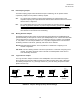
EIA 422 or 485
1-5
•
1
Trans/Rec Data −
−−
− [B/B’]
•
1
Transmitted Data −
−−
− [B] (Link lnput)
•
2
Trans/Rec Data + [A/A’]
•
2
Transmitted Data + [A] (Link Input)
•
3
No Connect
•
3
Received Data −
−−
− [B’] (Link Output)
•
4
No Connect
•
4
Received Data + [A’] (Link Output)
•
5
Signal Ground
•
5
Signal Ground
•
6
No Connect
•
6
No Connect
•
7
No Connect
•
7
No Connect
•
8
No Connect
•
8
No Connect
•
9
Chassis Ground
•
9
Chassis Ground
FIGURE 2. Data Port Pin Assignments
24132413
IED
T+
T-
R+ R-
REP
OFF
REP
OFF
IED
T+
T-
R+ R-
OFF Mode Repeat Mode
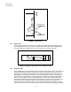
FIGURE 3. Data Signal Path
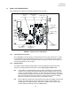
1.2.3 Mode Jumpers
The Mode Jumpers enable the repeater function in the "ON" position and disables it in the
"OFF" position. Note Figure 3 for data path.
ON: The repeater function available in the Link/Repeater is enabled. This function converts
the optical signal received on the R optical port to an electrical signal and delivers this
signal to the appropriate pins of the 9 pin connector, as well as, re-transmits the signal
optically out the Link/Repeater's T optical port.
OFF: The repeater function available in the Link/Repeater is disabled. The Link/Repeater
converts the optical signal received on the R optical port to an electrical signal and
delivers this signal to the appropriate pin of the 9 pin connector, and does not re-
transmit the signal optically out the Link/Repeater's T optical port.
FD MODE
HD
FD
HD MODE
HD
FD