
User's Manual

Model CH45
EIA 422 or 485
1-4
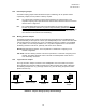
1.2 MODEL CH45 LINK/REPEATERS
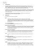
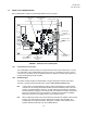
Each Link/Repeater consists of the following elements shown in Figure 1.
Data Coupling
Jumpers
HD/FD Jumpers
Biasing Resistor
Jumpers
Logic Invert
Jumper
Repeat Jumper
ST Fiber
Connectors
Diagnostic LED's
DB 9 Electrical
Connector
FIGURE 1. Elements of the Link/Repeater
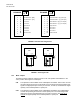
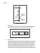
1.2.1 9 pin Data Port D-connector
The Link/Repeater connects directly to an IED's EIA 422 or 485 communication port. The pin
out configuration of the Link/Repeater is shown in Figure 2. If the IED's port is not a 9 pin D-
connector or if the IED's pin out configuration differs, an adapter is required. (See Figure 4 for
Factory Default Settings of All Jumpers)
1.2.2 HD/FD Jumpers
The HD/FD Jumpers adapt the Link/Repeater to accept independent transmit and receive
channels or a single shared transmit/receive channel. (All 4 jumpers must be set.)
HD: In this position, the Link/Repeater accepts a shared transmit/receive communication
channel such as normally associated with EIA 485 2 wire standards. When in the HD
position, the Link/Repeater is "listening" for data signals both optically and electrically
and automatically configures to the correct state. This position is normally used for EIA
485 2 wire connections and only half-duplex or simplex communication is available.
Multi-drop networks may be either Peer-to- Peer or Master / Slave.
FD: When independent transmit and receive electrical channels are available, select the FD
position. This will normally be used for EIA 422 or EIA 485 4 wire standards. The
Link/Repeater can support full duplex, half duplex or simplex communication in this
position. Multi-drop networks may only be Master/Slave.