
User's Manual
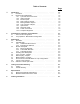

Table of Contents
Page
1. Introduction . . . . . . . . . . . . . . . . . . . . . . . . . . . . . . . . 1-1
1.1 Definitions . . . . . . . . . . . . . . . . . . . . . . . . . . . . . 1-1
1.2 Model CH45 Link/Repeater . . . . . . . . . . . . . . . . . . . . . 1-4
1.2.1 9 pin Data Port D-Connector . . . . . . . . . . . . . . . . 1-4
1.2.2 HD/FD Jumpers . . . . . . . . . . . . . . . . . . . . . . . 1-4
1.2.3 Mode Jumpers . . . . . . . . . . . . . . . . . .. . . . . . . 1-5
1.2.4 Data Coupling Jumpers . . . . . . . . . . . . . . . . . . . . 1-6
1.2.5 Biasing Resistor Jumpers . . . . . . . . . . . . . . . . . . 1-6
1.2.6 Logic Inversion Jumpers . . . . . . . . . . . . . . . . . . . 1-6
1.2.7 Optical Ports . . . . . . . . . . . . . . . . . . . . . . . . . 1-7
1.2.8 Diagnostic LEDs . . . . . . . . . . . . . . . . . . . . . . . 1-7
1.2.9 Power Connections . . . . . . . . . . . . . . . . . . . . . 1-8
1.2.10 Peripheral Equipment . . . . . . . . . . . . . . . . . . . . 1-8
2. Configurations, Operation, and Installation . . . . . . . . . . . . . . . 2-1
2.1 Point-to-Point Configuration . . . . . . . . . . . . . . . . . . . . 2-2
2.2 Loop Operation - Master/Slave Configuration . . . . . . . . . . . 2-7
3. Applications . . . . . . . . . . . . . . . . . . . . . . . . . . . . . . . . 3-1
3.1 Data Rate . . . . . . . . . . . . . . . . . . . . . . . . . . . . . 3-1
3.2 Optical Budget . . . . . . . . . . . . . . . . . . . . . . . . . . . 3-1
3.2.1 Cable Attenuation Factors . . . . . . . . . . . . . . . . . . 3-1
3.2.2 Extending the Distance . . . . . . . . . . . . . . . . . . . . 3-2
3.3 Number of Repeats . . . . . . . . . . . . . . . . . . . . . . . . 3-2
3.3.1 Effects of Data Rate . . . . . . . . . . . . . . . . . . . . . 3-3
3.3.2 Pulse Width Distortion . . . . . . . . . . . . . . . . . . . . 3-3
3.3.3 Temperature Effect . . . . . . . . . . . . . . . . . . . . . . 3-4
3.4 Powering the Link/Repeater . . . . . . . . . . . . . . . . . . . . 3-4
3.5 Logic Inversion Jumpers . . . . . . . . . . . . . . . . . . . . . . 3-4
3.6 Data Coupling Jumpers . . . . . . . . . . . . . . . . . . . . . . 3-5
3.7 Biasing Resistor Jumpers . . . . . . . . . . . . . . . . . . . . . . 3-5
3.8 Echo Control for EIA 485 Master in Loop Configurations . . . . . . . 3-5
3.9 Type of Communication . . . . . . . . . . . . . . . . . . . . . . 3-5
3.10 Selection of Fiber Optic Cable . . . . . . . . . . . . . . . . . . . 3-6
4. Testing and Trouble Shooting . . . . . . . . . . . . . . . . . . . . . . 4-1
4.1 Testing . . . . . . . . . . . . . . . . . . . . . . . . . . . . . . . 4-1
4.2 Trouble Shooting . . . . . . . . . . . . . . . . . . . . . . . . . . 4-1
5. Specifications . . . . . . . . . . . . . . . . . . . . . . . . . . . . . . . 5-1
5.1 Electrical and Optical Specifications . . . . . . . . . . . . . . . . 5-1
5.2 Mechanical Dimensions of the CH45 . . . . . . . . . . . . . . . 5-2
6. Ordering Information . . . . . . . . . . . . . . . . . . . . . . . . . . . . 6-1