
User's Manual

Models CH45
EIA 422 or 485
4-1
4. TESTING AND TROUBLE SHOOTING
4.1 TESTING
Model CH45 Link/Repeater is easily tested. Testing the unit requires transmitting and receiving data while
observing that the diagnostic LEDs are illuminating in the proper sequence.
To test whether a unit is transmitting and receiving correctly, set the FD/HD Jumpers to the FD position.
Insert a short fiber jumper between its "T" and "R" optical ports, power the unit and transmit a signal,
noting that all four diagnostic LEDs illuminate during communications.
To test the units in a loop configuration, two Link/Repeaters are required. Connect two short jumper fibers
from the "T" optical port of each Link/Repeater to the "R" optical port of the other. Set the Mode Jumpers
on one of the units to ON and the other to OFF (Note: the FD/HD Jumpers of this unit must be in the FD
position for testing). The unit with the Mode Jumpers in the OFF position is the Master. Power both units.
Using the Master, transmit and receive data through the other unit in the repeat mode. Observe the
diagnostic LEDs illumination patterns during communication.
Note
If interconnecting EIA 485 optically to RS232, the NORM / INVERT Jumpers must be in the
INVERT position.
If the IED’s design biases A (“+”) high and B (“-“) low (a “steady” illuminated TE light, with no
data flowing, will indicate this), then the NORM / INVERT Jumpers must be set to the INVERT
position.
If a master of a master/slave loop is operating in the HD mode (EIA 485), refer to Section 3.6 for
special system requirements for the control of the echo.
Models CH45
When not connected to an IED and in the repeat mode, the Link/Repeater should have Chassis Ground
(pin 9) connected to Signal Common (pin 5). If these pins are not tied together, noise could be induced
into the fiber loop. This is also necessary when servicing an IED in order to keep the fiber loop and the
Link/Repeater operational.
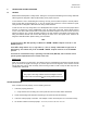
WARNING
The jumper connecting Chassis Ground and Signal Common
should be disconnected before reconnecting Model CH45 to an
IED.
TROUBLE SHOOTING
If the unit does not work properly, use the following check list:
1. Is the unit properly powered?
a. Verify that the unit is receiving the correct power and the red “PWR” LED is illuminated.
2. Check that the diagnostic LEDs are responding to the optical and electrical activity.
3. Is the unit mated properly to the IED? If an adapter is used, check that pins are connected correctly.
4. Are the fiber cables connected properly? "T" to "R"; not "R" to "R" nor "T" to "T".