
User's Manual
Models CH45
EIA 422 or 485
3-5
In addition, one can connect DYMEC-DynaStar Models CH43, 5843 or 5844 (RS-232 Link / Repeaters) to
the Models CH45, 5845 or 5846 and achieve RS-232 to EIA 422 or 485 format conversion directly in the
fiber connection without the need of external converter devices. However, the following condition must be
accounted for. In RS-232, the logic state is inverse to the physical layer, i.e. a logic high produces a
physical low. When connecting RS-232 protocol, this logic to physical layer inversion must be reversed or
it will cause a “light on” situation in the quiescent state in the Model CH45. Again, the Logic Jumper can
be set in the INVERT position to correct this situation.
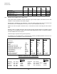
3.6 DATA COUPLING JUMPERS
The Data Coupling Jumpers are located on the unit (See Figure 1) and is standard on all Model CH45
Link / Repeaters. The Jumper allows the user to select AC or DC input data coupling on the DB9
connector for various network configurations. It is set in the AC position (factory default). When the
Jumper is set to the DC position, the input electrical signal is DC coupled to the internal logic.
AC coupling imposes a 1200 baud minimum data rate but in addition decouples any “lock-up” problems
on the connected IED from propagating through the network. DC coupling allows DC level signals or baud
rates below 1200 to be used but care must be taken in loop networks that the quiescent state of all
connected IED’s allow for a light off on the fiber optic side of the CH45. If the IED’s quiescent state leaves
the Fiber optic turned on see section 3.5.
3.6 BIASING RESISTOR JUMPERS
The Biasing Resistor Jumpers are located on the unit (See Figure 1) and is standard on all Model CH45
Link / Repeaters. The Jumper allows the user to select 10K Ohm or 300 Ohm biasing resistors on the
DB9 connector for various network configurations. It is set in the 330 Ohm position (factory default).
When the Jumper is set to the 10K Ohm position, the electrical input loading on the 422/485 bus is
reduced.
Biasing resistors are used in 422/485 networks to guarantee valid logic levels are on the bus when the
output driver circuitry is in the Tri-State mode. If biasing is not used or available there is a chance that
electrical noise on the lines will be misinterpreted as valid data. This is NOT to be confused with
termination resistors.
3.8 ECHO CONTROL FOR 2 WIRE EIA 485 MASTERS IN LOOP CONFIGURATIONS
Model CH45 is designed to continuously listen, both electrically and optically, for data signals. Since the
path is shared for transmit and receive, only one function may occur at any given interval in time. The
Model CH45 is designed to give priority to data signals received optically to those being transmitted
electrically assuming that the software logic is managing data traffic.
However, in loop configurations, a special situation occurs if the Master IED is operating 2 wire EIA 485
(HD). The echo of its transmissions can be received back to the Master so fast that it arrives before the
transmission is completed and a data collision will occur. Echo control must be implemented for each 2
wire IED that can become a Master in any loop configuration.
3.9 TYPE OF COMMUNICATION
Model CH45 Link/Repeaters support the following types of asynchronous communications:
Simplex - Transmission only or receive only
Half Duplex - Sequential transmit and receive
Full Duplex - Simultaneous transmit and receive