
User's Manual

Model CH45
EIA 422 or 485
2-9
2.2.1 Installation
1. Set the HD/FD Jumper to the appropriate position for each Link/Repeater and its respective
IED.
2. Set the Mode Jumper to “OFF” position on the Master. Set the Mode Jumpers of all the
Slave units to the "ON" position.
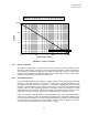
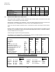
3. Set the Data Coupling Jumpers for the appropriate position based on the data rate used in
the communication network
4. Set the Logic Inversion Jumper to the appropriate position based on the communication
network
5. Insert the CH45 into an open slot in the 3900 Chassis and then energize the power source
to the 3900 Chassis (See the Installation Sheet for the 3900 Chassis for powering
Instructions). The Link/Repeater Card is now powered.
6. Connect the Link/Repeater to the IED's RS-422/485 communication port (including any
adapter that may be needed).
7. Connect the Fiber Optic Cables (T of one device to R of the second device).
8. The units are now installed and operating.
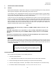
9. Verify operation using the diagnostic LEDs. (See Figure 7).
WARNING
When installing a Model CH45 Link/Repeater, an earth Ground must be
attached to the Ground Stud on the rear of the case of the 3900 Chassis before
connecting to power. Failure to follow this procedure may result in electrical
shock to personnel.
NOTE
The diagnostic LEDs only illuminate when there is signal traffic and are not illuminated during
signal "quiet" times. If during quiet time, TE and TO are illuminated, it suggests either a polarity
reversal (pin 2 with pin 1) or that the IED is biased pulling the “A” (+) line with respect to the “B” (-)
line. After checking the polarity on the connections, refer to Section 3.5.
The diagnostic LEDs may "flicker" when data is passing. This is normal operation.