
User's Manual


Model CH45
EIA 422 or 485
2-3
NOTE
The diagnostic LEDs only illuminate when there is signal traffic and are not illuminated during
signal "quiet" times. If during quiet time, TE and TO are illuminated, it suggests either a polarity
reversal (pin 2 with pin 1) or that the IED is biased pulling the “A” (+) line with respect to the “B”
(-) line. After checking the polarity on the connections, refer to Section 3.5.
The diagnostic LEDs may "flicker" when data is passing. This is normal operation.
APPLICATION NOTE
The Point-to-Point concept can be used to create an "optical bus" network. This can be useful
for those situations where the software in the Master has not been written in such a way that it
can handle the return of the transmitted echo that occurs in loop networks.
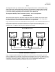
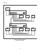
Figure 9 shows the connections for a Master/Slave EIA 422 “optical bus”. Note that EIA 422 Standards do not
permit multiple transmitters to be connected together as the outputs can not be tri-stated. In this
configuration, all Slaves hear the Master’s transmission, but only the Master hears the response from the
addressed slave. The Master must always be the first IED in the network.
2
4
13
24
1
3
Typical Slave
T+
T-
R+ R-
Master
T+
T-
R+ R-
Last Slave
T+
T-
R+ R-
REP
OFF
REP
OFF
REP
OFF
REP
OFF
EIA 422 Master/Slave
24132413
FIGURE 9. EIA 422 Bus Configuration
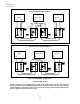
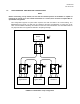
Figure 10 depicts an EIA 485 multiple drop “optical bus" for both 4 wire and 2 wire systems. The 4 wire
system is a Master/ Slave configuration. All the Slaves hear the Master’s poll, but only the Master can hear
the addressed Slave’s response and the Master must be the first IED in the network. However, in the 2 wire
configuration, the system is capable of operating as Peer to Peer or Master/Slave. All IEDs hear all
communications and the Master may be located at any point in the network.