
User's Manual


Models CH45
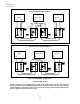
EIA 422 or 485
2-1
Master
T+
T-
R+ R-
Last Slave
T+
T-
R+ R-
REP
OFF
REP
OFF
2413 2413
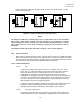
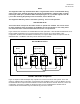
FIGURE 8. Point-to-Point Configuration
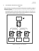
2.1.1 Installation
1. Set the HD/FD Jumper to the appropriate position for each Link/Repeater and its respective IED.
2. Set the Mode Jumper on both of the units to the "OFF" position.
3. Set the Data Coupling Jumpers for the appropriate position based on the data rate used in the
communication network
4. Set the Logic Inversion Jumper to the appropriate position based on the communication network
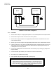
5. Insert the CH45 into an open slot in the 3900 Chassis and then energize the power source to the
3900 Chassis (See the Installation Sheet for the 3900 Chassis for powering Instructions). The
Link/Repeater Card is now powered.
6. Connect the Link/Repeater to the IED's RS-232 communication port (including any adapter that
may be needed).
7. Connect the Fiber Optic Cables (T of one device to R of the second device).
8. The units are now installed and operating.
9. Verify operation using the diagnostic LEDs. (See Figure 7).
WARNING
When installing a Model CH45 Link/Repeater, an earth Ground must be
attached to the Ground Stud on the rear of the case of the 3900 Chassis
before connecting to power. Failure to follow this procedure may result in
electrical shock to personnel.