
User's Manual

Model CH45
EIA 422 or 485
1-7
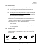
T Optical Port
R Optical Port
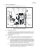
FIGURE 5. Optical Ports
1.2.7 Optical Ports
There are two optical ports, T and R. The T optical port transmits data signals optically to the
next Link/Repeater. The R port receives the optical data signal from another Link/Repeater's T
optical port. Each port is fitted with an "ST" type receptacle for connecting the FOC
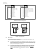
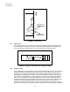
FIGURE 6. Diagnostic LED positions on faceplate of CH45
1.2.8 Diagnostic LEDs
Each Link/Repeater is equipped with four green diagnostic LEDs (See Figure 6). They represent
the electrical transmit (TE), optical transmit (TO), electrical receive (RE), and optical receive
(RO) paths. These LEDs, when illuminated, show that the appropriate path is active. When the
Link/Repeater is transmitting, both TE and TO LEDs will illuminate to show the transmit path
active. When the Link/Repeater is receiving light signals, both RO and RE LEDs will illuminate.
If the unit is in the repeat mode and receiving light, the RO, RE and TO LEDs will illuminate
because the signal is being re-transmitted out the optical port, as well as, being delivered to the
D-connector. LEDs only illuminate when the path is active; powering of the unit does not
illuminate these LEDs unless their path is active. When data is present on the paths, the LEDs
may "flicker"; this is normal. The diagnostic LEDs may be used for trouble shooting by observing