
Instruction Manual

Rev. 5/09 -3.29- TFXP
4-20 mA Test
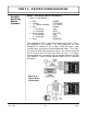
ISO-MOD:
Rate Pulse
Module
(Optional)
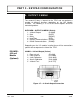
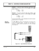
4-20 TST -- 4-20mA Output Test
Allows a simulated value to be output from the 4-20 mA module. By
incrementing this value, the 4-20 mA output will transmit the
indicated current value.
NOTE: This test is only available when the 4-20 mA module is set
up to source current.
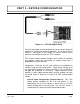
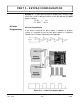
The Rate Pulse Output Module is utilized to transmit information to
external counters and PID systems via a frequency output that is
proportional to system flow rate. Independent zero and span
settings are established in software using the flow measuring range
entries. Output resolution of the module is 12-bits (4096
discrete
points) and the maximum output frequency setting is 2,500
Hz.
The pulse width is designed to give a 50% duty cycle. The module
has two output modes, turbine meter simulation and “open
collector”. The turbine meter simulation sources a non-ground
referenced saw-tooth waveform with a maximum amplitude of
approximately 500 mV p-p. The open collector output utilizes a 0.21
Ohm FET output that is rated to operate at 100 V and 1 A
maximum. If the open collector output is utilized, an external
voltage source and limit resistor must be present.
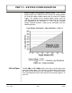
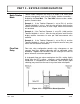
RATE -- Rate Pulse (Value)
1. Flow at 0 Hz (FL 0H)
2. Flow at 2.5k Hz (FL 25KH)
The
FL 0H
and
FL 25KH
entries are used to set the span of the
0 to
2.5k Hz frequency output. These entries are volumetric rate
units that are equal to the volumetric units configured as
Engineering Rate Units and Engineering Units Rate Interval entered
on pages 3.13 and 3.14.
Example 1: In a bi-directional system, to span the 0 to 2.5k Hz
output from -100 GPM to +100 GPM, with 1.25k Hz being 0 GPM,
set the FL 100H and FL 25KH inputs as follows:
FL 0H = -100.0
FL 25KH = 100.0
PART 3 - KEYPAD CONFIGURATION