
Instruction Manual

Rev. 5/09 - 2.9 - TFXP
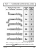
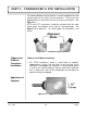
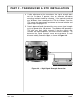
The spacing between the transducers is measured between the two
spacing marks on the sides of the transducers. These marks are
approximately 3/4 inch back from the nose of the transducer. See
Figure 2.3.
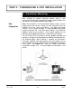
DTTS and DTTC transducers should be mounted with the cable
exiting within
±45 degrees
of the side of a horizontal pipe. See
Figure 2.2 on page 2.8. On vertical pipes the orientation is not
critical.
V-Mount and W-Mount Installation
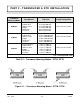
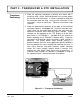
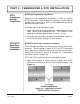
1. For DTTN transducers, place a single bead of couplant,
approximately 1/2 inch (12 mm) thick, on the flat face of the
transducer. See Figure 2.4. Generally, a silicone-based grease
is used as an acoustic couplant, but any grease-like substance
that is rated not to “flow” at the temperature that the pipe may
operate at will be acceptable.
Figure 2.4 — Application of Couplant
Application of
Couplant
Figure 2.3 — Transducer Spacing Marks
V-Mount and
W-Mount
Transducer
Installation
PART 2 - TRANSDUCER & RTD INSTALLATION