Series TFXP Transit Time Ultrasonic Flow Meter Operations & Maintenance Manual
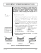
BEFORE OPERATING THE TFXP Important Notice! The TFXP flow meter is equipped with a lead-acid Gel Cell battery. This battery will require charging before initial operation. Apply power, utilizing the enclosed 12 volt DC output line power converter or auto-style power cord, to the TFXP for a period of 1624 hours prior to using the product for the first time. The power converter connects to the DC IN +12V socket connection located on the side of the enclosure. See Figure 1.1.
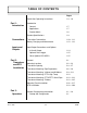
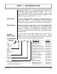
TABLE OF CONTENTS Pages Quick-Start Operating Instructions Part 1 Introduction Connections Inputs and Outputs Part 2 Transducer and RTD Installation Part 3 Operation Rev. 5/09 1.4 - 1.6 Introduction General 1.7 Applications 1.7 Product Matrix 1.8 Product Specifications 1.9 Transmitter Connections 1.10 - 1.11 Battery Charging and Maintenance 1.12 - 1.13 Input/Output Connections and Options 4-20 mA Output 1.14 Optional Data Logger 1.15 Other Optional ISO-MODs 1.15 General 2.
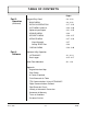
TABLE OF CONTENTS Pages Part 3 Operation (continued) Keypad Entry Detail 3.4 - 3.33 BASIC MENU 3.4 - 3.16 DATALOG OPERATION 3.17 - 3.23 OUT2 MENU 4-20 mA 3.24 - 3.30 Optional Input/Output 3.31 - 3.35 SENSOR MENU 3.36 SECURITY MENU 3.36 - 3.37 SERVICE MENU 3.37 - 3.39 Signal Strength 3.37 Setting ZERO Flow 3.38 DISPLAY MENU Part 4 Software 3.39 - 3.40 Software Utility Operation ULTRALINK™ 4.1 - 4.14 Data Logger 4.15 - 4.17 Heat Flow Addendum A.1 - A.
QUICK-START OPERATING INSTRUCTIONS This manual contains detailed operating instructions for all aspects of the TFXP instrument. The following condensed instructions are provided to assist the operator in getting the instrument configured and measuring as quickly as possible. This pertains to basic operation only. If specific instrument features are to be used or if the installer is unfamiliar with this type of instrument, refer to the appropriate section in the manual for complete details. 1.
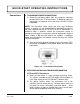
QUICK-START OPERATING INSTRUCTIONS Connections 2. TRANSDUCER/POWER CONNECTIONS A. Route the transducer cables from the transducer mounting location back to the TFXP transmitter. If additional cable and connections are required, ensure that they are RG59 75 Ohm compatible. NOTE: The transducer cable carries low level, high frequency signals. In general, it is not recommended to add additional cable to the cable supplied with the DTTN, DTTH or DTTS transducers.
QUICK-START OPERATING INSTRUCTIONS C. Apply a single 1/2" (12 mm) bead of couplant grease to the upstream transducer and secure it to the pipe with a mounting strap. D. Apply acoustic couplant grease to the downstream transducer and press it onto the pipe using hand pressure at the lineal distance calculated in Step 1. E. Move the transducer slowly around the mounting area until the highest signal strength is observed. Secure with a mounting strap at this location. DTTS and DTTC Transducers A.
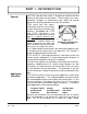
PART 1 - INTRODUCTION General The TFXP ultrasonic flow meter is designed to measure the fluid velocity of liquid within closed conduit. The transducers are a noncontacting, clamp-on or clamp-around type, which will provide benefits of non-fouling operation and ease of installation. TFXP transit time flow meters utilize two transducers that function as both ultrasonic transmitters and receivers. See Figure 1.4.
PART 1 - INTRODUCTION temperature of 250 °F (121 °C). High temperature DTTH transducers can operate to a pipe surface temperature of 350 °F (177 °C). The DTTS small pipe transducers can be used to a pipe surface temperature of 185 °F (85 °C) and the DTTC high temperature small pipe transducers are rated for 250 °F (121 °C). User Safety The TFXP employs modular construction and provides electrical safety for the operator. The display face contains voltages no greater than 10 VDC.
PART 1 - SPECIFICATIONS TRANSMITTER Power Requirements Internal 12 V lead-acid Gel Cell battery provides 24 hrs of continuous operation @ 20 °C. Charging: Wall mount power converter. 115 or 230 VAC 50/60 Hz ±15% VA max; 12-15 VDC @ 2.5 VA max Velocity Range -40 to +40 FPS (-12 to +12 MPS) Inputs/Outputs All output modules are optically isolated from earth and system grounds. One module and one data logger may be installed.
PART 1 - TFXP TRANSMITTER CONNECTIONS Transmitter Installation After unpacking, it is recommended to save the shipping carton and packing materials in case the instrument is stored or reshipped. Inspect the equipment and carton for damage. If there is evidence of shipping damage, notify the carrier immediately.
PART 1 - TFXP TRANSMITTER CONNECTIONS Electrical Connections It is highly recommended that the internal battery in the TFXP be fully charged before using the meter for the first time. Details covering this procedure are located on page 1.1 of this manual. 1. The connectors located on the side of the TFXP consist of three 1/4-turn BNC-type and one 5.5 mm power plug.
PART 1 - TFXP TRANSMITTER CONNECTIONS Battery Charging and External Power Sources The 12 volt DC power converter and 12 volt auto-style power cord connect to the socket connection located on the side of the enclosure. See Figure 1.5 on page 1.11. A fully charged battery will provide up to 24 hours of continuous operation before recharging will be necessary. When the battery level has decreased to a point where recharging is required, the LOW BATTERY indicator will brightly illuminate on the front panel.
PART 1 - TFXP TRANSMITTER CONNECTIONS NOTE: The TFXP will automatically enter a low power consumption mode approximately 1-1/2 minutes after the LOW BATTERY indicator illuminates. This circuit prevents excessive discharge of the internal battery. • If the TFXP is stored for prolonged periods of time, monthly charging is recommended. • If the TFXP is stored for prolonged periods of time, store at a temperature below 70 ºF (21 ºC).
PART 1 - TFXP TRANSMITTER CONNECTIONS Standard 4-20 mA Output The standard 4-20 mA output may be replaced with one of the following five ISO-MODs: dual-relay, rate pulse, RS232C, RS485 and heat flow (RTD). TFXP supports one ISO-MOD input/output module in addition to the optional data logger. All modules are field configurable by utilizing the keyboard or ULTRALINK™ interface. Field wiring connections to ISO-MODs are quick and easy using pluggable terminals.
PART 1 - TFXP TRANSMITTER CONNECTIONS Optional Data Logger A 200,000-point Data Logger* is located within the weather-tight pocket on the faceplate of the flow meter. See Figure 1.7. Loosen the three thumbscrews located in the corners of the pocket cover and rotate the cover to expose the Data Logger Module. The logger stores time-stamped, high resolution (16-bit) data at user selected intervals ranging from 1 to 30,000 (8.33 hours) seconds.
PART 1 - INTRODUCTION NOTES Rev. 5/09 -1.
PART 2 - TRANSDUCER & RTD INSTALLATION General The transducers that are utilized by the TFXP contain piezoelectric crystals for transmitting and receiving ultrasonic signals through walls of liquid piping systems. DTTN and DTTH transducers are relatively simple and straightforward to install, but spacing and alignment of the transducers is critical to the system's accuracy and performance. Extra care should be taken to ensure that these instructions are carefully executed.
PART 2 - TRANSDUCER & RTD INSTALLATION 1. Mounting Location The first step in the installation process is the selection of an optimum location for the flow measurement to be made. For this to be done effectively, a basic knowledge of the piping system and its plumbing are required. An optimum location is defined as: Rev. 5/09 • A piping system that is completely full of liquid when measurements are being taken.
PART 2 - TRANSDUCER & RTD INSTALLATION Table 2.1 1 — Piping Configuration and Transducer Positioning 1 The TFXP system will provide repeatable measurements on piping systems that do not meet these requirements, but the accuracy of these readings may be influenced to various degrees. Rev. 5/09 - 2.
PART 2 - TRANSDUCER & RTD INSTALLATION 2. Transducer Spacing TFX transit time flow meters are sold with four different transducer types: DTTN, DTTH, DTTS and DTTC. Meters that utilize DTTN or DTTH transducer sets consist of two separate sensors that function as both ultrasonic transmitters and receivers. DTTS and DTTC transducers integrate both the transmitter and receiver into one assembly that fixes the separation of the piezoelectric crystals.
PART 2 - TRANSDUCER & RTD INSTALLATION Transducer Mounting Mode Pipe Material Pipe Size W-Mount Plastic (all types) Carbon Steel Stainless Steel Copper Ductile Iron Cast Iron1 2-4 in (50-100 mm) 2-4 in (50-100 mm) 2-4 in (50-100 mm) 2-4 in (50-100 mm) Not recommended Not recommended V-Mount Plastic (all types) Carbon Steel Stainless Steel Copper Ductile Iron Cast Iron 4-12 in (100-300 mm) 4-12 in (100-300 mm) 4-12 in (100-300 mm) 4-30 in (100-750 mm) 2-12 in (50-300 mm) 2-12 in (50-300 mm) Z-Mount
PART 2 - TRANSDUCER & RTD INSTALLATION Size Frequency Transducer Mounting Mode Size Frequency Transducer DTTSnP 1/2 2 MHz 3/4 2 MHz DTTSnC DTTSnP W 1-1/4 2 MHz DTTSnT DTTSnP DTTSnP W 1-1/2 2 MHz DTTSnT 2 MHz DTTSnC DTTSnC W W DTTSnT DTTSnP 1 DTTSnC DTTSnT DTTSnC Mounting Mode W 2 DTTSnT 1 MHz 2 MHz DTTSnP DTTSnC DTTSnT V W NOTE: DTTS transducer designation refers to both DTTS and DTTC transducer types. Table 2.
PART 2 - TRANSDUCER & RTD INSTALLATION Important! Enter all of the data on this list, save the data and reset the TFX before mounting transducers The following information is required before programming the instrument. NOTE: Much of the data relating to material sound speed, viscosity and specific gravity is preprogrammed into the TFX flow meter. This data only needs to be modified if it is known that a particular liquid’s data varies from the reference value.
PART 2 - TRANSDUCER & RTD INSTALLATION 3. Transducer Mounting After selecting an optimal mounting location (Step 1) and successfully determining the proper transducer spacing (Step 2) the transducers may now be mounted onto the pipe. Pipe Preparation Before the transducers are mounted onto the pipe surface, an area slightly larger than the flat surface of each transducer must be cleaned of all rust, scale and moisture.
PART 2 - TRANSDUCER & RTD INSTALLATION The spacing between the transducers is measured between the two spacing marks on the sides of the transducers. These marks are approximately 3/4 inch back from the nose of the transducer. See Figure 2.3. DTTS and DTTC transducers should be mounted with the cable exiting within ±45 degrees of the side of a horizontal pipe. See Figure 2.2 on page 2.8. On vertical pipes the orientation is not critical. Figure 2.
PART 2 - TRANSDUCER & RTD INSTALLATION Transducer Positioning 2. Place the upstream transducer in position and secure with a mounting strap. Straps should be placed in the arched groove on the end of the transducer. A screw is provided to help hold the transducer onto the strap. Verify that the transducer is true to the pipe — adjust as necessary. Tighten the transducer strap securely. 3. Place the downstream transducer on the pipe at the calculated transducer spacing. See Figure 2.5.
PART 2 - TRANSDUCER & RTD INSTALLATION 4. If after adjustment of the transducers the signal strength does not rise to above 5 percent, then an alternate transducer mounting method should be selected. If the mounting method was W-Mount, then reconfigure the TFX for V-Mount, reset the TFX, move the downstream transducer to the new location and repeat Step 3 on page 2.10. 5. Certain pipe and liquid characteristics may cause signal strength to rise to greater than 195 percent.
PART 2 - TRANSDUCER & RTD INSTALLATION DTTH Transducers for High Temperature DTTH High Temperature Transducers Mounting of high temperature transducers is similar to standard DTTN transducers. High temperature installations require acoustic couplant that is rated not to “flow” at the temperature that will be present on the pipe surface. Installation consists of the following steps: 1. Apply a thin coating of high temperature acoustic couplant to the entire surface of the transducer face.
PART 2 - TRANSDUCER & RTD INSTALLATION 2. On horizontal pipes, mount the transducer in an orientation so that the cable exits at ±45° from the side of the pipe. Do not mount with the cable exiting on either the top or bottom of the pipe. On vertical pipes the orientation is not critical. See Figure 2.2 on page 2.8. 3. Tighten the wing nuts or “U” bolts so that the grease begins to flow out from the edges of the transducer and from the gap between the transducer halves. Do not over tighten. 4.
PART 2 - TRANSDUCER & RTD INSTALLATION Figure 2.10 — Bisecting the Pipe Circumference 3. Crease the paper at the fold line. Mark the crease. Place a mark on the pipe where one of the transducers will be located. See Figure 2.2 on page 2.8 for acceptable radial orientations. Wrap the template back around the pipe, placing the beginning of the paper and one corner in the location of the mark. Move to the other side of the pipe and mark the pipe at the ends of the crease.
PART 2 - TRANSDUCER & RTD INSTALLATION 5. For DTTN transducers, place a single bead of couplant, approximately 1/2 inch (12 mm) thick, on the flat face of the transducer. See Figure 2.4 on page 2.9. Generally, a siliconebased grease is used as an acoustic couplant, but any greaselike substance that is rated to not “flow” at the temperature that the pipe may operate at will be acceptable. 6. Place the upstream transducer in position and secure with a stainless steel strap or other.
PART 2 - TRANSDUCER & RTD INSTALLATION Figure 2.11 — Z-Mount Transducer Placement Mounting Track Installation Rev. 5/09 D010-2102-010 Mounting Track Installation 1. The D010-2102-010 transducer mounting track is used for pipes that have outside diameters between 2 and 10 inches (50-250 mm). If the pipe is outside of that range, select a standard V-Mount or Z-Mount mounting method. 2. Install the single mounting rail on the side of the pipe with the stainless steel bands provided.
PART 2 - TRANSDUCER & RTD INSTALLATION Figure 2.12 — D010-2102-010 Mounting Track Installation Rev. 5/09 6. Secure with the thumb screw. Ensure that the screw rests in the counter bore on the top of the transducer. (Excessive pressure is not required. Apply just enough pressure so that the couplant fills the gap between the pipe and transducer.) 7. Place the second transducer in between the mounting rails near the dimension derived in the Transducer Spacing section.
PART 2 - TRANSDUCER & RTD INSTALLATION 4. RTD INSTALLATION For typical installations, the length of RTD wire should equal the length of the flow transducer cable. Ensure that the length of wire included with the RTDs is adequate to reach from the supply and return pipes to the location of the TFX transmitter. If the length of wire is insufficient, wire can be added on but a small temperature offset will result.
PART 2 - TRANSDUCER & RTD INSTALLATION Figure 2.13 — Surface Mount RTD Installation Insertion RTD Installation Insertion RTD Installation Insertion RTDs are typically installed through 1/4" compression fittings and isolation ball valves. 1. It is recommended that insertion RTDs be mounted downstream of the flow measurement transducers to avoid causing flow instability in the flow measurement region. 2. Insert the RTD into the flow stream so that a minimum of 0.25" of the probe tip extends into the pipe.
PART 2 - TRANSDUCER & RTD INSTALLATION Figure 2.14 — Insertion RTD Installation Figure 2.15 — Insertion RTD Orientation - Horizontal Pipes Rev. 5/09 - 2.
PART 3 - STARTUP AND CONFIGURATION Before Starting the Instrument NOTE: The TFX flow meter system requires a full pipe of liquid before a successful startup can be completed. Do not attempt to make adjustments or change configurations until a full pipe is verified. NOTE: If Sonotemp® silicone grease was utilized as a couplant, a curing time is not required. However, if Dow 732 or another permanent RTV was used, the adhesive must fully cure before power is applied to the instrument.
PART 3 - KEYPAD CONFIGURATION General After installation of the transducers and connection of appropriate cabling to the TFX, keypad configuration of the instrument can be performed. All entries are saved in non-volatile FLASH memory and will be retained in the event of power loss. The TFX can be configured through the keypad interface or by using the ULTRALINK™ Windows® compatible software utility. (See Part 4 of this manual for software details.
PART 3 - KEYPAD CONFIGURATION “Soft Key” menu items will be displayed immediately above the two keys located in the lower corners of the graphics display. See Figure 3.1 on page 3.2. Soft key functions can be any of the following: The MENU soft key places the meter into Programming mode from Run mode. The ACK soft key is used to Acknowledge a condition that requires user intervention. The ACCEPT soft key is used to Accept configuration parameter changes.
PART 3 - KEYPAD CONFIGURATION Figure 3.2 — 2 Line vs 4 Line Display In the RUN mode pressing the SELECT soft key highlights one of the display lines. Successively pressing the SELECT soft key cycles through all of the display lines. Use the UP/DOWN arrow keys to select desired parameter. When the correct choice is shown, press the SELECT soft key once again to lock in the choice.
PART 3 - KEYPAD CONFIGURATION 5. Sensor Menu – The Sensor menu is used to select the sensor type (i.e. DTTN, DTTH, etc.) 6. Security Menu – The Security menu is utilized for resetting totalizers, resetting the operating system and revising security passwords. 7. Service Menu – The Service menu contains system settings that are used by service personnel for troubleshooting. 8. Display Menu – The Display menu is used to configure meter display functions.
PART 3 - KEYPAD CONFIGURATION Transducer Mounting Method XDCR MNT -- Transducer Mounting Method (Choice) 1. V 2. W 3. Z Selects the mounting orientation for the transducers. The selection of an appropriate mounting orientation is based on pipe and liquid characteristics. See Part 2 – Transducer & RTD Installation in this manual. Pipe Diameter PIPE OD -- Pipe Outside Diameter Entry (Value) 1. ENGLSH (Inches) 2.
PART 3 - KEYPAD CONFIGURATION 16. St Steel 302/303 17. St Steel 304/316 18. St Steel 410 19. St Steel 430 20. PFR 21. Titanium 22. Other (SS 303) (SS 316) (SS 410) (SS 430) (PFR) (TITAMN) (OTHER) This list is provided as an example. Additional pipe materials may have been added. Select the appropriate pipe material from the list or select Other if the material is not listed. Pipe Sound Speed PIPE SS -- Speed of Sound in the Pipe Material (Value) 1. ENGLSH (Feet per Second) 2.
PART 3 - KEYPAD CONFIGURATION If a pipe material was chosen from the Pipe Mat list, a nominal value for relative roughness in that material will be automatically loaded. If the actual roughness is known for the application piping system and that value varies from the automatically loaded value, the value can be revised. If Other was chosen as Pipe Mat, a Pipe R must also be entered. Liner Thickness LINER T -- Pipe Liner Thickness Entry (Value) 1. ENGLSH (Inches) 2.
PART 3 - KEYPAD CONFIGURATION Liner Sound Speed LINER SS -- Speed of Sound in the Liner (Value) 1. ENGLSH (Feet per Second) 2. METRIC (Meters per Second) Allows adjustments to be made to the speed of sound in the liner. If the Units value was set to Englsh, the entry is in FPS (feet per second). Metric entries are made in MPS (meters per second). If a liner was chosen from the Liner Mat list, a nominal value for speed of sound in that media will be automatically loaded.
PART 3 - KEYPAD CONFIGURATION Fluid Sound Speed FLUID SS -- Speed of Sound in the Fluid (Value) 1. ENGLSH (Feet per Second) 2. METRIC (Meters per Second) Allows adjustments to be made to the speed of sound in the liquid. If the Units value was set to Englsh, the entry is in FPS (feet per second). Metric entries are made in MPS (meters per second). If a fluid was chosen from the Fl Type list, a nominal value for speed of sound in that media will be automatically loaded.
PART 3 - KEYPAD CONFIGURATION If a fluid was chosen from the Fl Type list, a nominal value for specific gravity in that media will be automatically loaded. If the actual specific gravity is known for the application fluid and that value varies from the automatically loaded value, the value can be revised. If Other was chosen as Fl Type, a Sp Grvty may need to be entered if mass flows are to be calculated.
PART 3 - KEYPAD CONFIGURATION Specific Heat Capacity BTU/lb °F Temperature Ethylene Glycol Solution (% by Volume) °F °C 25 30 40 50 60 65 100 -40 -40 n/a n/a n/a n/a 0.68 0.70 n/a 0 -17.8 n/a n/a 0.83 0.78 0.72 0.70 0.54 40 4.4 0.91 0.89 0.845 0.80 0.75 0.72 0.56 80 26.7 0.92 0.90 0.86 0.82 0.77 0.74 0.59 120 84.9 0.93 0.92 0.88 0.83 0.79 0.77 0.61 160 71.1 0.94 0.93 0.89 0.85 0.81 0.79 0.64 200 93.3 0.95 0.94 0.91 0.87 0.83 0.81 0.
PART 3 - KEYPAD CONFIGURATION Transducer Spacing XDCR SPAC -- Transducer Spacing Calculation (Value) 1. ENGLSH (Inches) 2. METRIC (Millimeters) This value represents the one-dimensional linear measurement between the transducers (the upstream/downstream measurement that runs parallel to the pipe). This value is in inches if Englsh was selected as Units; in millimeters if Metric was selected. This measurement is taken between the alignment marks which are scribed into the sides of the transducer blocks.
PART 3 - KEYPAD CONFIGURATION 8. Liquid Barrels (LIQ BARR) [31.5 Gallons] 9. Feet (FEET) 10. Meters (METERS) 11. Pounds (LB) 12. Kilograms (KG) 13. British Thermal (BTU) Units 14. Thousands of BTUs (MBTU) 15. Millions of BTUs (MMBTU) 16. Tons (TON) Select a desired engineering unit for flow rate measurements. Engineering Units RATE INTERVAL RATE INT -- Time Interval for Flow Rate (Choice) 1. Seconds (SEC) 2. Minutes (MIN) 3. Hour (HOUR) 4.
PART 3 - KEYPAD CONFIGURATION 13. Millions of BTUs 14. Tons (MMBTU) (TON) Select a desired engineering unit for flow accumulator (totalizer) measurements. Engineering Units TOTAL Exponent TOTL E -- Flow Totalizer Exponent Value (Choice) E-1 to E6 Utilized for setting the flow totalizer exponent. This feature is useful for accommodating a very large accumulated flow. The exponent is a ×10n multiplier, where "n" can be from -1 (×0.1) to +6 (×1,000,000). Table 3.
PART 3 - KEYPAD CONFIGURATION Maximum Flow Rate MAX RATE -- Maximum Flow Rate Settings (Value) Rate Unit/Rate Interval A maximum volumetric flow rate setting is entered to establish filter software settings. Volumetric entries will be in the Engineering Rate Units and Interval selected on pages 3.13 and 3.14. Set Max Rate to the highest (positive) flow rate expected in the piping system.
PART 3 - KEYPAD CONFIGURATION ISO-MOD: Data Logger Module (Optional) I/O module bay number 1 is reserved exclusively for the ISO Data Logger module. The 200,000 event data logger/electronic stripchart recorder can be configured to match most user applications. The logger stores timestamped, high resolution (16-bit) data at user selected intervals ranging from 1 to 30,000 (8.33 hours) second(s).
PART 3 - KEYPAD CONFIGURATION NOTE: The logger will not automatically go to the next location if the previous location is filled. In this case when the location exceeds 30,000 data points the oldest points will be discarded in favor of new points. This is the classic FIFO memory stack.
PART 3 - KEYPAD CONFIGURATION Logging Interval DATALOG INT -- Datalog Interval (Value) ((Sec)) 1 to 30,000 From the Datalog Operation menu, adjust the time Interval between readings. Interval values between 1 and 30,000 seconds are acceptable. For reference there are: 60 seconds in 1 minute 300 seconds in 5 minutes 1,800 seconds in 30 minutes 3,600 seconds in 1 hour 30,000 seconds in 8.33 hours Table 3.6 on page 3.
PART 3 - KEYPAD CONFIGURATION Example No. INTERVAL Seconds DURATION Hours Operated Samples Collected 1 1 6 21,600 2 10 72 (3 days) 25,920 3 60 (1 min) 480 (20 days) 28,800 4 300 (5 min) 2,016 (12 wks) 24,192 5 1,800 (30 min) 8,760 (1 yr) 17,520 6 3,600 (1 hr) 8,760 (1 yr) 8,760 7 18,000 (5 hr) 26,280 (3 yr) 17,520 Table 3.
PART 3 - KEYPAD CONFIGURATION 3. DATALOG MAINTENANCE Datalog Maintenance permits files to be deleted from the data logger module. The menu contains three options for deleting files. Erase All (Choice) 1. Yes 2. No Deletes all files stored in the data logger. Erase First (Choice) 1. Yes 2. No Deletes the first file generated. This would be the oldest file in the loggers memory. Erase Last (Choice) 1. Yes 2. No Deletes the last file generated. This would be the newest file in the loggers memory.
PART 3 - KEYPAD CONFIGURATION This number will appear in the “Name” column on the computer screen before data is downloaded. 4. 5. 6. 7. Confirm Data Logger Operation Stop Data Logger Rev. 5/09 NOTE: The firmware will accept any Datalog Location number between 1 and 30,000 however only 1 thru 16 are valid locations. Accept Datalog Interval number shown or choose another number between 1 and 30,000 seconds as the logging interval. Use the UP/DOWN arrow keys to change the logging interval values.
PART 3 - KEYPAD CONFIGURATION NOTES: Data logger must be stopped before downloading data. If data logger is not stopped before downloading data, an erroneous file will be recorded on the data logger. The serial cable should not be connected to the data logger while data logger is running. If the serial cable is connected to the data logger while data logger is running, error message 3007 will appear on the display and data will be lost.
PART 3 - KEYPAD CONFIGURATION 4. OUTPUT 2 MENU The second I/O bay is internal to the TFXP and can perform a number of different functions depending on the ISO Module installed. The following is a list of the current options and their menu designations. OUT2 MEN -- OUTPUT #2 MENU (Choice) 1. 2. 3. 4. 5. 6.
PART 3 - KEYPAD CONFIGURATION Figure 3.8 — 4-20 mA Output Wiring The 4-20 mA output can be configured to source current (internally powered) or sink current (externally powered). The choice of sink or source is configured at the factory to source current unless otherwise instructed at the time the TFX is ordered. The 4-20 mA output module interfaces with virtually all recording and logging systems by transmitting an analog current that is proportional to system flow rate.
PART 3 - KEYPAD CONFIGURATION External Power Configuration (Current Sink): If the 4-20 mA output module was ordered from the factory for external power the 4-20 mA module requires power from an external DC power supply. The voltage of the external power source must be sufficient to power the module and drive the loop load.
PART 3 - KEYPAD CONFIGURATION Example 1: To span the 4-20 mA output from -100 GPM to +100 GPM, with 12 mA being 0 GPM, set the FL 4MA and FL 20MA inputs as follows: FL 4MA = -100.0 FL 20MA = 100.0 Example 2: To span the 4-20 mA output from 0 GPM to +100 GPM, with 12 mA being 50 GPM, set the FL 4MA and FL 20MA inputs as follows: FL 4MA = 0.0 FL 20MA = 100.0 The 4-20 mA ISO-MOD is factory calibrated and should not require adjustment unless it is replaced.
PART 3 - KEYPAD CONFIGURATION NOTE: The CAL 4MA and CAL 20MA entries should not be used in an attempt to set the 4-20 mA range. Utilize the FL 4MA and FL 20MA, detailed on page 3.26, for this purpose. Procedure: 1. Disconnect any wires presently connected to the spring clips on the end of the 4-20 mA output cable. Connect the ammeter in series with the spring clips on the end of the 4-20 mA output cable. NOTE: Be sure to connect the multimeter test leads for current measurement.
PART 3 - KEYPAD CONFIGURATION 4-20 mA Test 4-20 TST -- 4-20mA Output Test Allows a simulated value to be output from the 4-20 mA module. By incrementing this value, the 4-20 mA output will transmit the indicated current value. NOTE: This test is only available when the 4-20 mA module is set up to source current.
PART 3 - KEYPAD CONFIGURATION Example 2: To span the 0 to 2.5k Hz output from 0 GPM to +100 GPM, with 1.25k Hz being 50 GPM, set the FL 0H and FL 25KH inputs as follows: FL 0H = 0.0 FL 25KH = 100.0 K-Factor Programming K-Factor Programming If the device receiving the pulse output is capable of K-factor scaling, it is possible to use the rate pulse output in a totalizing function. See K-Factors Explained in the Appendix. Figure 3.11 — Rate Pulse Output Wiring Rev. 5/09 -3.
PART 3 - KEYPAD CONFIGURATION ISO-MOD: Dual Relay Module (Optional) RELAY -- Dual Relay (Choices and Values) RELAY 1 AND RELAY 2 1. None 2. Totalizer a. Totalizer Multiplier 3. Flow a. On Setting b. Off Setting 4. Signal Strength a. On Setting b. Off Setting 5. Errors (NONE) (TOTALIZE) (TOT MULT) (FLOW) (ON) (OFF) (SIG STR) (ON) (OFF) (ERRORS) Two independent SPDT (single-pole, double-throw) Form C relays are contained in this module.
PART 3 - KEYPAD CONFIGURATION Batch/Totalize Mode Totalize mode configures the relay(s) to output a 50 mSec pulse (contact changeover) each time the display totalizer increments – divided by the Total Mult. The Total Mult value must be a whole, positive, numeric value. Example 1: If the Totalizer Exponent is set to E0 (×1) and the Totalizer Multiplier is set to 1, then the relay will pulse each time the totalizer increments one count, or each single, whole measurement unit totalized.
PART 3 - KEYPAD CONFIGURATION Signal Strength Alarm The Sig Str alarm will provide an indication that the flow meter signals between the transducers have fallen to a point where flow measurements may not be possible. It can also be used to indicate that the pipe has emptied. Like the flow rate alarm described on page 3.13, the signal strength alarm requires that two points be entered, establishing an alarm deadband. A valid switch point exists when the ON> is a value lower than OFF<.
PART 3 - KEYPAD CONFIGURATION Figure 3.14 — RTD Connections ISO-MOD: RS232C Module (Optional) RS232C -- RS232C (Choice) Baud Rate (RS232 BA) 1. 1200 Baud (1200) 2. 2400 Baud (2400) 3. 9600 Baud (9600) 4. 19,200 Baud (19200) The RS232C module can be interfaced with serial communication ports of PCs, PLCs and SCADA systems. This module runs a proprietary digital protocol, detailed in the Appendix of this manual, that is used to monitor flow rate information in piping systems.
PART 3 - KEYPAD CONFIGURATION ISO-MOD: RS485 Module (Optional) RS485 -- RS485 (Choices and Values) RS485 Mode (RS485 MO) 1. Slave (SLAVE) 2. Master (MASTER) Baud Rate (RS485 BA) 1. 1200 Baud (1200) 2. 2400 Baud (2400) 3. 9600 Baud (9600) 4. 19,200 Baud (19200) Device Address (Addr) (1-127) The RS485 module allows up to 126 TFX systems to be daisychained on a single three-wire cable network. Communications are through a proprietary digital protocol, detailed in the Appendix of this manual.
PART 3 - KEYPAD CONFIGURATION 5. SEN MENU -- SENSOR MENU The SEN MENU is utilized to select the type of transducer that will be interfaced with the TFX. Select the appropriate transducer from the list and save the configuration. If the transducer selection is modified, a system reset is required. Transducer Type XDUCER TYP -- Transducer Type (Choices and Values) 1. DTTN Standard Transducers (DTTN Clamp-On) 2. DTTH High Temperature Transducers (DTTH Clamp-On) 3. DTT1500 (DTT 1500) 4.
PART 3 - KEYPAD CONFIGURATION Change Password CH PSWD? -- Change the Security Password (Value) 0-9999 By changing the Security Password from 0 to some other value (any value between 1 to 9999), configuration parameters will not be accessible without first entering that value when prompted. If the value is left at 0, no security is invoked and unauthorized changes could be made. 7.
PART 3 - KEYPAD CONFIGURATION MINIMUM RATE SETTING 0.0 MAXIMUM RATE SETTING 1,000.0 SUBSTITUTE FLOW SETTING DISPLAY READING DURING ERRORS 0.0 0.000 -500.0 500.00 50.0 0.000 -100.0 200.0 33.3 0.000 0.0 1,000.0 -5.0* -50.00 * NOTE: ULTRALINK™ is required to set values outside of 0.0 - 100.0. Table 3.8 — Typical Zero Settings Factory Default Zero Calibration SET ZERO -- Calibrating Zero Flow (Choice) 1. No 2.
PART 3 - KEYPAD CONFIGURATION the meter. This is not as desirable as the Set Zero and should only be used with large pipes. 1. Press EDIT at the Reset Zero prompt, use the arrow keys to make the display read Yes. 2. Press ACCEPT. Correction Factor COR FTR -- Correction Factor (Value) (0.500 – 1.500) This function can be used to make the TFX system agree with a different or reference flow meter by applying a correction factor/ multiplier to the readings and outputs.
PART 3 - KEYPAD CONFIGURATION Back Light Timeout BACK LIGHT -- Back Light Timeout (Choice) 1. 30 Seconds (30 Sec) 2. 1 Minute (1 Min) 3. 5 Minutes (5 Min) 4. On (Always On) The LED backlighting is used to assist the operator in viewing the display in poorly lit areas. The backlighting, when activated, doubles the power consumption of the flow meter. If left on continuously, the charge in the battery will be depleted much more rapidly than if the backlighting is only activated for short periods of time.
PART 4 - SOFTWARE UTILITIES Important Notice! The TFXP flow meter can be used with two software utilities, ULTRALINK™ and Data Logger. The ULTRALINK™ utility is used for configuration, calibration and communication with the TFXP flow meter. The Data Logger utility is used for uploading and translating data accumulated in the data logger module located in the pocket on the front faceplate of the flow meter.
PART 4 - SOFTWARE UTILITIES Initialization Connect the infrared communications adapter to a PC communication port and point the communicator at the TFXP infrared window located in the lower right-hand corner of the keypad. If meter is ordered with either ISO-MOD RS232 or ISOMOD RS485 options, connect the PC communications cable directly to the DB-9 connection located on the side of the TFXP meter. Click on the Communications button in the menu bar. Next click on Initialize.
PART 4 - SOFTWARE UTILITIES Figure 4.2 — “Data Display” Screen Pipe and Liquid Configuration The first screen that appears after clicking the Configuration button is the BASIC tab. See Figure 4.3 on page 4.5. Basic Tab General Units allows selection of either English (U.S.) or Metric units of measure. If measurements of the pipe are to be entered in inches, select English. If measurements are to be entered in millimeters, select Metric.
PART 4 - SOFTWARE UTILITIES Transducer Mount selects the orientation of the transducers on the piping system. See Part 2 of this manual and Table 2.2 on page 2.5 for detailed information regarding mounting modes for particular pipe and liquid characteristics. Whenever Transducer Mount is changed, a download command and subsequent microprocessor reset or flow meter power cycle must be conducted.
PART 4 - SOFTWARE UTILITIES Figure 4.3 — Basic Tab Layout Flow Units Configuration Flow Tab Flow Rate Units are selected from the pull-down lists. Select an appropriate rate unit and time from the two lists. Totalizer Units are selected from the pull-down lists. Select an appropriate totalizer unit and totalizer exponent. The totalizer exponents are in scientific notation and permit the eight digit totalizer to accumulate large values before the totalizer “rolls over” and starts again at zero. Table 4.
PART 4 - SOFTWARE UTILITIES Exponent Display Multiplier E-1 × 0.1 E0 × 1 (no multiplier) E1 × 10 E2 × 100 E3 × 1,000 E4 × 10,000 E5 × 100,000 E6 × 1,000,000 Table 4.1 — Totalizer Exponent Values The Damping value is increased to improve stability of the flow rate readings. Damping values are decreased to allow the flow meter to react faster to changing flow rates.
PART 4 - SOFTWARE UTILITIES Substitute Flow is used to provide an indication and output that signifies that an error exists with the flow meter or its setup. It is set as a percentage between MIN Flow and MAX Flow. In a unidirectional system this value is typically set to zero to indicate zero flow while in an error condition. In a bi-directional system, the percentage can be set such that zero is displayed in an error condition.
PART 4 - SOFTWARE UTILITIES Time Domain Filter adjusts the number of raw data sets (the wave forms viewed on the ULTRALINK™ Diagnostics Screen) that are averaged together. Increasing this value will provide greater damping of the data and slow the response time of the flow meter. This filter is not adaptive – it is operational to the value set at all times. Low Signal Cutoff is a duplicate entry from Flow tab. Adjusting this value adjusts the value on the Flow tab.
PART 4 - SOFTWARE UTILITIES Flow Filter MinHysteresis sets a minimum hysteresis window that is invoked at sub 0.25 FPS (0.08 MPS) flow rates, where the “of rate” Flow Filter Hysteresis is very small and ineffective. This entry is entered in picoseconds and is differential time. If very small fluid velocities are to be measured, increasing the Flow Filter MinHysteresis value can increase reading stability.
PART 4 - SOFTWARE UTILITIES Output Configuration Output Tab The entries made in the Output tab establish input and output calibration and ranges for ISO-MOD modules installed in the TFX flow meter. If a module was ordered from and installed at the factory, then the Output tab will contain information and configuration for that module. If a module has been changed from the factory setting, a configuration error will result.
PART 4 - SOFTWARE UTILITIES Calibration/Test is used to adjust the factory calibration span of the 4-20 mA output and to test the output. The 4-20 mA output is factory calibrated and should not require adjustment in the field. If the module is replaced or if recalibration is required, the following procedure is used to calibrate the span of the module: 1. Connect a milliamp meter serially within the 4-20 mA module output. 2. Check the Calibration/Test box. 3. Select the 4 mA Calibration box. 4.
PART 4 - SOFTWARE UTILITIES Setting Zero and Calibration ULTRALINK™ contains a powerful multi-point calibration routine that can be used to calibrate the TFX flow meter to a primary measuring standard in a particular installation. To initialize the threestep calibration routine, click on the Calibration button located on the top of the ULTRALINK™ Data Screen. The display shown in Figure 4.7 will appear.
PART 4 - SOFTWARE UTILITIES Figure 4.8 — Calibration (Page 2 of 3) The final screen (Page 3 of 3) shown in Figure 4.9 on page 4.14 allows multiple actual flow rates to be recorded by the TFX. To calibrate a point, establish a stable, known flow rate (verified by a real-time primary flow instrument), enter the actual flow rate in the Figure 4.9 window and click the Set button.
PART 4 - SOFTWARE UTILITIES Figure 4.9 — Calibration (Page 3 of 3) Saving the Configuration Saving Meter Configuration on a PC The complete configuration of the flow meter can be saved from the Configuration screen. Select File Save button located in the lower left-hand corner of the screen and name the file. Files are saved as a *.dcf extension.
PART 4 - SOFTWARE UTILITIES Using the Data Logger Software During the installation of ULTRALINK™, a file called Data Logger was installed and its icon will appear in the ULTRALINK™ folder under Program Files. Double-click on the Datalog.exe icon to start the utility. The screen shown in Figure 4.10 will appear as the computer is attempting to establish communications with the logger module. Figure 4.
PART 4 - SOFTWARE UTILITIES Figure 4.11 — File Uploading Figure 4.12 — Saving Data Logger Files Rev. 5/09 -4.
PART 4 - SOFTWARE UTILITIES The data logger module contains a real-time clock that can be set by clicking the Clock button on the top task bar (see Figure 4.13). Activating the window compares the data logger clock to the clock located in the PC. Adjustments can be made and uploaded to the logger. Figure 4.13 — Data Logger Clock Rev. 5/09 -4.
PART 4 - SOFTWARE UTILITIES NOTES Rev. 5/09 -4.
HEAT FLOW ADDENDUM General The TFX flow meter with the optional RTD (heat flow) Module installed is designed to measure the rate and quantity of heat delivered to a given building, area or heat exchanger. The instrument measures the volumetric flow rate of the heat exchanger liquid (water, water/glycol mixture, brine, etc.), the temperature at the inlet pipe and the temperature at the outlet pipe.
HEAT FLOW ADDENDUM Installation Installation 1. Follow the instructions outlined in the standard TFX manual for proper installation of the ultrasonic transducers. After installation, verify that the signal strength is sufficient for stable flow readings and, if possible, perform a Zero flow calibration on the pipe. Please note that all readings require a full pipe of liquid. 2. Select areas on the inlet and outlet pipes where the RTDs will be mounted.
HEAT FLOW ADDENDUM 5. Route a cable from the electrical junction box back to the TFX flow meter. Connect the RTDs as illustrated in Figure A.2. Note that the SNS1 and DRV1 wires originate from the same location on the RTD. Figure A.2 — RTD Connection Programming Transmitter Programming 1. The RTDs included with the TFX heat flow option have been factory calibrated and are marked with an identification as to which terminal, #1 or #2, the RTD has been calibrated.
HEATFLOW FLOWADDENDUM DDENDUM HEAT UNIT list. Select the appropriate RATE INTERVAL from the list (seconds, minutes, hours, days). Be aware that the instrument can only display values as large as 99,999,999. 4. Select an appropriate TOTALIZER UNIT from the list; BTUs, MBTU, MMBTU, or TON . 5. From the main display, three values can be accessed that may aid in troubleshooting the heat flow instrument.
HEAT FLOW ADDENDUM Accuracy Accuracy The accuracy of BTU measurements relies on two separate measurements – mass flow and difference temperature. The BTU meter can measure volumetric flow to within about 1% of reading accuracy. For example if the liquid is chilled water in the range of 40-60 °F, the influences on mass flow accuracy within this temperature range, with a volumetric flow meter are on the order of 0.073% potential error.
HEAT FLOW ADDENDUM NOTES Rev. 5/09 -A.
APPENDIX
V V Page 1 BSC MENU DATALOG UNITS ENGLSH METRIC LINER T ENGLSH (INCHES) METRIC (MM) FLUID VI CP XDCR MNT V W Z LINER TYPE * EBONITE MORTAR HDPE LDPE POLYPRO POLYSTY RUBBER TAR EPXY TEFLON OTHER SP GRVTY UNITLESS PIPE OD ENGLSH (INCHES) METRIC (MM) PIPE WT ENGLSH (INCHES) METRIC (MM) PIPE MAT * ACRYLIC ALUMINUM BRASS CARB ST CAST IRN COPPER DCTL IRN FBRGLASS PYREX NYLON HDPE LDPE POLYPRO PVC/CPVC PVDF SS 303 SS 316 SS 410 SS 430 TITANM PFR OTHER PIPE SS ENGLSH (FPS) METRIC (MPS) PIPE R (RELATIVE R
V V Page 2 OUT2 MEN OUT2 OPTIONS 4-20MA FL 4MA FL 20MA CAL 4MA CAL 20MA 4-20 TST RATE FL 0H FL 25KH RELAY RELAY 1 NONE TOTALIZE RTD RTD1 A TOT MULT RTD1 B FLOW ON RTD2 A OFF RTD2 B SIG STR ON OFF ERRORS RELAY 2 NONE TOTALIZE TOT MULT FLOW ON OFF SIG STR ON OFF ERRORS RTD RTD1 A RTD1 B RTD2 A RTD2 B SEC MENU SEN MENU RS485 RS485 MO SLAVE MASTER RS485 BA 1200 2400 9600 19200 ADDRESS 1-127 NONE TOT RES NO YES XDUCER TYP DTTN DTTH DTT 1500 DTTSnC DTTSnP RS232 RS232 MO HOST UIF RS232 BA 1200 2400 9600
TFX Error Codes Revised 2-22-2002 Code Number Description Correction 0001 Serial number not present Hardware serial number has become inoperative – system performance will not be influenced.
K-Factors Explained The K-factor (with regards to flow) is the number of pulses that must be accumulated to equal a particular volume of fluid. You can think each pulse as representing a small fraction of the totalizing unit. An example might be a K-factor of 1000 (pulses per gallon). This means that if you were counting pulses, when the count total reached 1000, you would have accumulated 1 Gallon of liquid. Using the same reasoning each individual pulse represents an accumulation of 1/1000 of a gallon.
Example 2 Known values are: Full Scale Flow Rate Full Scale Output Frequency = 85 GPM = 650 Hz 650 Hz x 60 sec = 39,000 pulses per min K-factor = 39,000 pulses per min = 458.82 pulses per gallon 85 GPM The calculation is a little more complex if velocity is used because you first must convert the velocity into a volumetric flow rate to be able to compute a K-factor.
4) What is the flow rate in GPM at 4.3 ft/sec. 0.384 gallons x 4.3 FPS x 60 sec (1min) = 99.1 GPM Now that the volumetric flow rate is know all that is needed is an output frequency to determine the K-factor. Known values are: Frequency Flow Rate = = 700 Hz (By measurement) 99.1 GPM (By calculation) 1) 700 Hz x 60 sec = 42,000 pulses per min 2) K-factor = 42,000 pulses per min = 423.9 pulses per gallon 99.
Fluid Properties Original Date: Revision: Revision Date: File: Fluid Acetate, Butyl Acetate, Ethyl Acetate, Methyl Acetate, Propyl Acetone Alcohol Alcohol, Butyl Alcohol, Ethyl Alcohol, Methyl Alcohol, Propyl Alcohol, Propyl Ammonia Anlline Benzene Benzol, Ethyl Bromine n-Butane Butyrate, Ethyl Carbon dioxide Carbon tetrachloride Chloro-benezene Chloroform Diethyl ether Diethyl Ketone Diethylene glycol Ethanol Ethyl alcohol Ether Ethyl ether Ethylene glycol Freon R12 Gasoline Glycerin Glycol Isobutanol Is
Oil, Castor Oil, Diesel Oil (Lubricating X200) Oil (Olive) Oil (Peanut) Paraffin Oil Pentane Petroleum 1-Propanol Refrigerant 11 Refrigerant 12 Refrigerant 14 Refrigerant 21 Refrigerant 22 Refrigerant 113 Refrigerant 114 Refrigerant 115 Refrigerant C318 Silicone (30 cp) Toluene Transformer Oil Trichlorethylene 1,1,1-Trichloro-ethane Turpentine Water, distilled Water, heavy Water, sea Wood Alcohol m-Xylene o-Xylene p-Xylene 0.97 0.80 0.91 0.94 0.626 0.876 0.78 1.49 1.52 1.75 1.43 1.49 1.56 1.46 1.62 0.99 0.
TFX Communications Using UltraLink The current implementation of the UltraLink software utility was originally developed for Windows 95, Windows 98, and Windows 2000 using a standard RS-232 port. These operating systems left the choice of serial ports much more in the users hands. The physical connection was also the age-old DB-9 serial connections found on all computers of the time. With the introduction of Windows XP using USB serial ports inputs connections became a little more troublesome.
This converter is required regardless of the operating system or the type of port on the computer. The next step up is the infrared connections used on TFXD, PE1, TFXP, HTTP, PE3, TFXM, PE2 transit time meters and MFX series mag probes. Do not confuse this with the general propose infrared ports built into many computers, calculators, and printers. To make a connection to UltraLink a dedicated IR device is required.
USB (Universal Serial Buss) Ports USB ports also come in a variety of physical configurations. The two most common are USB A and USB B. In most computers the USB A configuration is the most default. The first problem is the need to convert the RS-232 output to a USB format. Complicating issues even more is that there are two major flavors of USB implementations depending on the age of the computer.
The device manager window should look something like this. Communicating with UltraLink Once the com port properties are known the next step is to configure UltraLink to talk on the correct port with the correct device. Open UltraLink and from the main data display screen click on the Communications drop down in the menu bar. When the communications drop down opens choose Initialize. The initialize window has two fields to make choices from. The first choice is for the com port to be used.
The figure on the left shows a typical communications setup for a TFXL, HTTF, or PTTF. The TFXL, HTTF, and PTTF all use a standard RS232 com port type. The TFXD, PE1, TFXP, HTTP, PE3, TFXM, and PE2 primary communications link uses the IrDA Actisis 220L infrared communications adapter. A typical com port setup for this device would look similar to this. Once the com port and com port type have been entered press OK to finalize the initialization.
Verifying Communications There are several possible combinations of indicators that signal communications status. In the lower right hand corner of the Data Display screen there is a Comm box that can take on one of three values. A green OK means that the physical connection to the serial port is intact. A red Error indicates some kind of communications problem. A red Offline is saying that the connection between the computer and UltraLink has been turned off.
Digital Communications Protocol for TFX Flow Meters Host protocol A digital communications protocol is utilized. Each message is guarded with the standard CRC-16 error detection (C source code is included) The host protocol is a master-slave type protocol with the flowmeter being the slave. The messages have the following format: … A unit may be assigned an address that responds to (valid addresses are 1-7E). All devices respond to address 7F (ie.
Special codes The following special 65 and 66 codes are supported.
C Source Code Flow Data Definition struct FLOWDATA { short sSignalStrength; double dCurFlowRate; double dNetTotalizer; double dPositiveTotalizer; double dNegativeTotalizer; }; struct FLOWDATA_EX { short sSignalStrength; double dCurFlowRate; double dNetTotalizer; double dPositiveTotalizer; double dNegativeTotalizer; double dTemp1; double dTemp2; }; CRC-16 Calculations unsigned short crc_table[256] = { 0x0000, 0xC0C1, 0xC181, 0x0140, 0xC601, 0x06C0, 0x0780, 0xC741, 0xCC01, 0x0CC0, 0x0D80, 0xCD41, 0x0A00, 0xC
0x4400, 0x84C1, 0x8581, 0x4540, 0x8701, 0x47C0, 0x4680, 0x8641, 0x8201, 0x42C0, 0x4380, 0x8341, 0x4100, 0x81C1, 0x8081, 0x4040, }; unsigned short calculate_crc(const unsigned char *pv, int size) { unsigned short crc = 0xFFFF; for ( ;size-- ; pv++) { crc = (crc >> 8) ^ crc_table[(crc ^ *pv) & 0xFF]; } return crc; }
“STEEL, STAINLESS STEEL, P.V.C. PIPE” STANDARD CLASSES 1.315 1.660 1.900 2.375 2.875 3.500 ID 1.185 1.53 1.77 2.245 2.709 3.334 Wall 0.065 0.065 0.065 0.065 0.083 0.083 SCH 10 (Lt Wall) ID Wall 1.097 0.109 1.442 0.109 1.682 0.109 2.157 0.109 2.635 0.120 3.260 0.120 3.5 4 5 6 8 10 4.000 4.500 5.563 6.625 8.625 10.75 3.834 4.334 5.345 6.407 8.407 10.482 0.083 0.083 0.109 0.109 0.109 0.134 3.760 4.260 5.295 6.357 8.329 10.42 0.120 0.120 0.134 0.134 0.148 0.165 8.125 10.25 0.250 0.250 8.071 10.
“STEEL, STAINLESS STEEL, P.V.C. PIPE” STANDARD CLASSES Nominal Pipe Size Inches Outside Diameter 1 1.25 1.5 2 2.5 3 SCH 60 ID Wall X STG. SCH 80 1.315 1.660 1.900 2.375 2.875 3.500 ID 0.957 1.278 1.500 1.939 2.323 2.900 Wall 0.179 0.191 0.200 0.218 0.276 0.300 ID 0.957 1.278 1.500 1.939 2.323 2.900 Wall 0.179 0.191 0.200 0.218 0.276 0.300 3.5 4 5 6 8 10 4.000 4.500 5.563 6.625 8.625 10.75 7.813 9.750 0.406 0.500 3.364 3.826 4.813 5.761 7.625 9.75 0.318 0.337 0.375 0.432 0.500 0.500 3.
Ductile Iron Pipe (Standard Classes) Size (Inches) 3” 4” 6” 8” 10” 12” 14” 16” Class 51 52 53 54 55 56 O.D. 50 3.96 3.96 3.96 3.96 3.96 3.96 Wall 0.25 0.28 0.31 0.34 0.37 0.41 I.D. 3.46 3.40 3.34 3.28 3.22 3.14 O.D. 4.80 4.80 4.80 4.80 4.80 4.80 Wall 0.26 0.29 0.32 0.35 0.38 0.42 I.D. 4.28 4.22 4.16 4.10 4.04 3.93 O.D. 6.90 6.90 6.90 6.90 6.90 6.90 6.90 Wall 0.25 0.28 0.31 0.34 0.37 0.40 0.43 I.D. 6.40 6.34 6.28 6.22 6.16 6.
COPPER TUBING Nominal Diameter ½” 5⁄8” ¾” 1” 1¼” 1½” 2” 2½” 3” COPPER TUBING Copper & Brass Pipe ALUMINUM Nominal Diameter Copper & Brass Pipe K M O. D. 0.625 0.625 0.625 0.840 Wall 0.049 0.040 0.028 0.108 I.D. 0.527 0.545 0.569 0.625 O. D. 0.750 0.750 0.750 Wall 0.049 0.042 0.030 I.D. 0.652 0.666 0.690 O. D. 0.875 0.875 0.875 1.050 Wall 0.065 0.045 0.032 0.114 I.D. 0.745 0.785 0.811 0.822 O. D. 1.125 1.125 1.125 1.315 0. D. 5.125 5.125 5.
Cast Iron Pipe (Standard Classes) Size (Inches) 3” 4” 6” 8” 10” 12” 14” 16” 18” 20” Class D E A B C O.D. 3.80 3.96 3.96 3.96 Wall 0.39 0.42 0.45 0.48 I.D. 3.02 3.12 3.06 3.00 O.D. 4.80 5.00 5.00 5.00 Wall 0.42 0.45 0.48 0.52 I.D. 3.96 4.10 4.04 3.96 F G H Size (Inches) O.D. 24” 30” O.D. 6.90 7.10 7.10 7.10 7.22 7.22 7.38 7.38 Wall 0.44 0.48 0.51 0.55 0.58 0.61 0.65 0.69 I.D. 6.02 6.14 6.08 6.00 6.06 6.00 6.08 6.00 36” A B C 25.
FPS TO GPM CROSS - REFERENCE (Schedule 40) Nominal I.D. Pipe INCH (Inches) 1 1.5 2 2.5 3 3.5 4 4.5 5 5.5 6 6.5 7 7.5 8 8.5 9 1 1.05 2.6989 4.0484 5.3978 6.7473 8.097 9.4462 10.796 12.145 13.490 14.844 16.190 17.540 18.890 20.240 21.590 22.941 24.290 1.25 1.38 4.6620 6.9929 9.3239 11.655 13.99 16.317 18.648 20.979 23.310 25.641 27.970 30.300 32.630 34.960 37.300 39.627 41.958 1.5 1.61 6.3454 9.5182 12.691 15.864 19.04 22.209 25.382 28.555 31.730 34.900 38.070 41.250 44.420 47.
FPS TO GPM CROSS - REFERENCE (Schedule 40) Nominal I.D. Pipe INCH (Inches) 1 1.5 2 2.5 3 3.5 4 4.5 5 5.5 6 6.5 7 7.5 8 8.5 9 18 16.88 697.52 1046.3 1395.0 1743.8 2093.0 2441.3 2790.1 3138.8 3488.0 3836.3 4185.0 4534.0 4883.0 5231.0 5580.0 5928.9 6277.7 20 18.81 866.14 1299.0 1732.0 2165.3 2598.4 3031.5 3464.6 3897.6 4330.7 4763.8 5196.8 5629.9 6063.0 6496.0 6929.1 7362.2 7795.3 24 22.63 1253.7 1880.0 2507.0 3134.1 3761.0 4387.8 5014.6 5641.5 6268.3 6895.1 7522.0 8148.8 8775.6 9402.
Limited Warranty and Disclaimer Dynasonics, division of Racine Federated Inc. warrants to the end purchaser, for a period of one year from the date of shipment from the factory, that all new transmitters and transducers manufactured by it are free from defects in materials and workmanship. This warranty does not cover products that have been damaged due to misapplication, abuse, lack of maintenance or improper installation.
RETURN OF EQUIPMENT/SALES INFORMATION CONTACTS AND PROCEDURES Customer Service/Application Engineer: If you have a question regarding order status, placing an order, reviewing applications for future purchases, or wish to purchase a new flow meter, please contact our new National Sales and Marketing Headquarters: DYNASONICS Division of Racine Federated Inc.
GENERAL TERMS AND CONDITIONS OF SALES 1. PAYMENT – Terms of payment are effective from the actual date of invoice. If, in the Seller’s opinion, the financial condition of the Buyer at any time – or any other circumstances – does not justify the incurrence of production costs of shipment on the terms of payment specified, the Seller may require partial or full payment in advance. Payment terms are net 30 days unless otherwise stated on invoice. 2. F.O.B.
Division of Racine Federated Inc. 8635 Washington Avenue Racine, WI 53406-3738 Toll-Free in North America Tel: 800-535-3569 Fax: 800-732-8354 Tel: 262-639-6770 Fax: 262-639-2267 www.dynasonics.com DYNASONICS is a registered trademark of Racine Federated Inc. ULTRALINK is a trademark of Racine Federated Inc. Windows, Vista and Excel are registered trademarks of Microsoft Corporation. Ultem is a registered trademark of General Electric Company. Vespel is a registered trademark of E. I.