Series TFXM Ultrasonic Multi-Channel Flow Meter Operations & Maintenance Manual REV 8/02
TABLE OF CONTENTS Pages Quick-Start Operating Instructions Part 1 Introduction 1.3-1.4 Introduction General 1.5 Applications 1.5 Model Matrix 1.6 Product Specifications 1.7 Transmitter Connections Part 1 Connections Part 1 - Inputs and Outputs Transmitter Limits and Installation 1.8-1.9 Power and Transducer Connections 1.9-1.12 Input/Output Connections and Options 4-20 mA Output 1.13 Dual Control Relay 1.14 Rate Pulse Output RS232C RS485 1.
TABLE OF CONTENTS Pages Part 3 Programming Startup and Configuration 3.1 General Programming Information 3.2-3.4 BASIC MENU 3.5-3.14 OUTPUT MENU 3.15-3.18 AUX COMM MENU 3.18-3.22 SENSOR MENU 3.23 SECURITY MENU 3.23 SERVICE MENU 3.24 Liquid Sound Speed 3.25 Signal Strength 3.25-3.26 Setting ZERO Flow 3.27 Correction Factor Entry 3.27-3.28 DISPLAY MENU Part 4 - Software Part 5 - MultiChannel 3.29 Software Utility Operation UltraLink 4.1-4.12 DataLink 4.13-4.
QUICK-START OPERATING INSTRUCTIONS This manual contains detailed operating instructions for all aspects of the TFXM instrument. The following condensed instructions are provided to assist the operator in getting the instrument started up and running as quickly as possible. This pertains to basic operation only. If specific instrument features are to be used or if the installer is unfamiliar with this type of instrument, refer to the appropriate section in the manual for complete details.
QUICK-START OPERATING INSTRUCTIONS TABLE 1.1 1. 2. 3. 4. 5. 6. * Transducer mounting method Pipe O.D. (Outside Diameter) Pipe wall thickness Pipe material Pipe sound speed* Pipe relative roughness* 7. 8. 9. 10. 11. 12. Pipe liner thickness Pipe liner material Fluid type Fluid sound speed* Fluid viscosity* Fluid specific gravity* Nominal values for these parameters are included within the TFXM operating system.
PART 1 - INTRODUCTION General The TFXM ultrasonic flow meter is designed to measure the fluid velocity of liquid within closed conduit. The transducers are a non-contacting, clamp-on type, which will provide benefits of nonfouling operation and ease of installation. TFXM transit time flowmeters utilize two transducers that function as both ultrasonic transmitters and receivers. The transducers are clamped on the outside of a closed pipe at a specific distance from each other.
PART 1 - INTRODUCTION User Safety The TFXM employs modular construction and provides electrical safety for the operator. The display face and keypad contains voltages no greater than 10 Vdc. The wiring access panel provides users access to wiring terminals without risking damage to flow meter circuits. Disconnect electrical power before opening the instrument enclosure.
PART 1 - SPECIFICATIONS Rev. 8/02 -1.
PART 1 - TRANSMITTER INSTALLATION Transmitter Installation After unpacking, it is recommended to save the shipping carton and packing materials in case the instrument is stored or reshipped. Inspect the equipment and carton for damage. If there is evidence of shipping damage, notify the carrier immediately. The enclosure should be mounted in an area that is convenient for servicing, calibration or for observation of the LCD readout. 1.
PART 1 - TRANSMITTER INSTALLATION 6 7 8 9 2 3 4 5 0 1 . +/- 10.44 (265.1) .20 (5.1) DIA 4 MOUNTING HOLES 10.55 (268.0) 11.00 (279.4) 4.18 (106.2) 11.34 (288.0) Figure 1.3 - TFX Transmitter Installation Dimensions To access terminal strips for electronic connections, loosen the six screws in the wiring access panel located on the bottom of the enclosure. Transducer Connections 1. Guide the transducer cables through the transmitter conduit holes located in the bottom of the enclosure.
Figure 1.4 TFXM Wiring Diagram PART 1 - TRANSMITTER INSTALLATION Rev. 8/02 -1.
PART 1 - TRANSMITTER INSTALLATION ters only have one measuring channel, so transducers will only be connected to the CH1 terminals. DTFXM2 flow meters have two measuring channels, so transducers will be connected to both the CH1 and CH2 terminals. See Figure 1.4. Secure wires by tightening to between 0.5 and 0.6 Nm of torque. NOTE: The transducer cables carry low level signals. It is typically not recommended to add additional cable to the factory supplied coaxial cables.
PART 1 - TRANSMITTER INSTALLATION the battery source from damage should a fault occur. See the Wiring Diagram located at Figure 1.4 . Uninterruptible Power Configuration Both AC and a 12 VDC battery power can be connected to the TFXM to facilitate an uninterruptible power source to the flow meter. The flow meter will operate on the AC power source until AC power is interrupted—at that point the flow meter will continue to operate on the battery until AC power is restored.
PART 1 - INPUT/OUTPUT CONFIGURATION General Series TFXM contains integrated RS485 communications, one 420 mA output per measurement channel and two SPDT relays per measurement channel. Other auxiliary input/output options are available. All outputs are 2,500 V optically isolated from TFXM power and Earth grounds -- eliminating the potential for ground loops and reducing the chance of severe damage in the event of an electrical surge.
PART 1 - INPUT/OUTPUT CONFIGURATION Max Loop Load = (External Supply Voltage - 5) 0.02 Cable used to transmit 4 -20 mA signals should be routed in wiring trays or conduits that carry instrumentation signals. It should not be run with AC power or other potential sources of noise. Very long cables can be accommodated, but the resistance of the wire must be added to the total loop load to ensure that adequate power is available to power the load.
PART 2 - TRANSDUCER POSITIONING General The transducers that are utilized by the Series TFXM contain piezoelectric crystals for transmitting and receiving ultrasound signals through walls of liquid piping systems. DTTN and DTTH transducers are relatively simple and straight-forward to install, but spacing and alignment of the transducers is critical to the system's accuracy and performance. Extra care should be taken to ensure that these instructions are carefully executed.
PART 2 - TRANSDUCER POSITIONING sides of the pipe and the sound crosses the pipe once. See Figures 2.1-2.3. This selection is based on pipe and liquid characteristics. The flowmeter operates by alternately transmitting and receiving a frequency modulated burst of sound energy between the two transducers and measuring the time interval that it takes for sound to travel between the two Table 2.
PART 2 - TRANSDUCER POSITIONING V-Mount Configuration transducers. Figure 2.1 - Transducer V-Mount W-Mount Configuration Figure 2.2 - Transducer W-Mount Rev. 8/02 - 2.
PART 2 - TRANSDUCER POSITIONING Z-Mount Configuration Figure 2.3 Z-Mount. Direct type — transducers mounted on opposite sides of the pipe. See Table 2.2 for a list of Initial Transducer Mounting Modes. Figure 2.3 - Transducer Z-Mount Rev. 8/02 - 2.
PART 2 - TRANSDUCER POSITIONING Table 2.2 Initial Transducer Mounting Modes Transducer Mount Mode Pipe Material Pipe Size Liquid Composition* W-mode (Weakest signal, longest time of flight) Plastic (all types) Carbon Steel Stainless Steel Copper Ductile Iron Cast Iron 2-6 in. (50-150 mm) 2-4 in. (50-100 mm) 2-6 in. (50-150 mm) 2-6 in.
PART 2 - TRANSDUCER POSITIONING 2. Transducer Spacing The TFXM system calculates proper transducer spacing by utilizing piping and liquid information entered by the user. This information can be entered via the keypad on TFXM or via the UltraLink Windows software utility. IMPORTANT: Since the time interval being measured is influenced by the transducer spacing, it is critical that the transducer spacing be measured on the pipe accurately to assure optimum performance from the TFXM system.
PART 2 - TRANSDUCER POSITIONING Keypad The TFXM can be configured through the keypad interface or by using the UltraLink Windows® software utility. Of the two methods of configuration, the UltraLink software utility provides more advanced features and offers the abililty to store and transfer meter configurations between TFXM meters. SOFT KEYS ARROW KEYS MEASUREMENT CHANNEL SELECTION INFRARED WINDOW Figure 2.
PART 2 - TRANSDUCER POSITIONING 1. The UP/DOWN ARROW keys are used to scroll through menus and configuration parameters. The ARROW keys can also be used to adjust parameter numerical values. In RUN mode the UP/DOWN ARROW keys are used to adjust the display contrast level. 2. The Numerical Keypad is used for entering numerical values. 3. The (soft)ACCEPT key is used to ?? accept configuration parameter changes. 5.
PART 2 - TRANSDUCER POSITIONING The BASIC menu contains all of the configuration parameters necessary to make the transducer spacing calculation. UNITS Entry UNITS ENGLSH METRIC Installs a global measurement standard into the operation of the instrument. The choices are either English or Metric measurements. ?? Select ENGLSH if all configurations (pipe sizes, etc.) are to be made in inches. Select METRIC if the meter is to be configured in millimeters.
PART 2 - TRANSDUCER POSITIONING Pipe O.D. Entry PIPE OD -- Pipe Outside Diameter Entry ENGLSH (Inches) METRIC (Millimeters) Enter the pipe outside diameter in inches if ENGLSH was selected as UNITS; in millimeters if METRIC was selected. Pipe Wall Entry PIPE WT -- Pipe Wall Thickness Entry ENGLSH (Inches) METRIC (Millimeters) Enter the pipe wall thickness in inches if ENGLSH was selected as UNITS; in millimeters if METRIC was selected.
PART 2 - TRANSDUCER POSITIONING (meters per second). If a pipe material was chosen from the PIPE MAT list, a nominal value for speed of sound in that material will be automatically loaded. If the actual sound speed rate is known for the application piping system and that value varies from the automatically loaded value, the value can be revised. If OTHER was chosen as PIPE MAT, a PIPE SS will need to be entered.
PART 2 - TRANSDUCER POSITIONING Liner Material Entry [If a LINER Thickness was selected] LINER MAT - Liner Material TAR EPOXY RUBBER MORTAR POLYPROPYLENE POLYSTYROL POLYSTYRENE POLYESTER POLYETHYLENE EBONITE TEFLON Other This list is provided as an example. Additional materials are being added continuously. Select the appropriate material from the list or select OTHER if the liner material is not listed.
PART 2 - TRANSDUCER POSITIONING BUTANE OTHER This list is provided as an example. Additional liquids are being added continuously. Select the appropriate liquid from the list or select OTHER if the liquid is not listed. Fluid Sound Speed Entry FLUID SS -- Speed of Sound in the Fluid ENGLSH (Feet per Second) METRIC (Meters per Second) Allows adjustments to be made to the speed of sound in the liquid. If the UNITS value was set to ENGLSH, the entry is in FPS (feet per second).
PART 2 - TRANSDUCER POSITIONING Fluid Specific Gravity Entry SP GRVTY -- Fluid Specific Gravity Entry unitless Allows adjustments to be made to the specific gravity (density) of the liquid. If a fluid was chosen from the FL TYPE list, a nominal value for specific gravity in that media will be automatically loaded. If the actual specific gravity is known for the application fluid and that value varies from the automatically loaded value, the value can be revised.
PART 2 - TRANSDUCER POSITIONING UltraLink Entry UltraLink Data Entry The UltraLink Windows®-based software utility provides an efficient means for entering piping and liquid parameters through the use of pop-up window/pull-down menu structures.
PART 2 - TRANSDUCER POSITIONING Transducer spacing appears here. Figure 2.5 UltraLink Windows-based software utility configuration screen. Rev. 8/02 - 2.
PART 2 - TRANSDUCER POSITIONING 3. Transducer Mounting After selecting an optimal mounting location, Step 1, and successfully determining the proper transducer spacing, Step 2, the transducers can now be mounted onto the pipe. The DTT transducers need to be properly oriented on the pipe to provide optimum reliability and performance. On horizontal pipes, the transducers should be mounted 180 radial degrees from one another and at least 45 degrees from the top-deadcenter and bottom-dead-center of the pipe.
PART 2 - TRANSDUCER POSITIONING Installation on Large Pipes Mounting Transducers in Z-Mount Configuration Installation on larger pipes requires careful measurements to the linear and radial placement of the DTT transducers. Failure to properly orient and place the transducers on the pipe may lead to weak signal strength and/or inaccurate readings. The section below details a method for properly locating the transducers on larger pipes.
PART 2 - TRANSDUCER POSITIONING transducer location) the dimension derived in Step 2, Transducer Spacing. Mark this location on the pipe. The two marks on the pipe are now properly aligned and measured. Figure 2.7 Bisecting the pipe circumference If access to the bottom of the pipe prohibits the wrapping of the paper around the circumference, cut a piece of paper to these dimensions and lay it over the top of the pipe. Length = Pipe O.D. x 1.57 Width = Spacing determined on Pages 2.14 or 2.
PART 2 - TRANSDUCER POSITIONING Transducer Mounting 1. Place a single bead of couplant, approximately 3/8 inch [6 mm] thick, on the flat face of the transducer. See Figure 2.8. Use Dow 732 for permanent and Dow 44 or Dow 111 for temporary (less than 12 months) installations. [For high temperature installations, utilize the Dow 112 and orange silicone pads that were shipped with the DTTH transducers. Apply the couplant to the transducer face as shown in Figure 2.
PART 2 - TRANSDUCER POSITIONING Lineal measurements are made from these lines. Figure 2.9 Z-Mode Transducer Mounting 3. Secure the transducer by tightening the stainless steel strap. (Excessive pressure is not required. Apply just enough pressure so that the couplant fills the gap between the pipe and transducer.
PART 2 - TRANSDUCER POSITIONING Mounting Track Installation Mounting Track Installation 1. Install the single mounting track on the pipe in an orientation suggested by Figure 2.5 (minus the rail mounted across the pipe) with the stainless steel bands provided. Orientation on vertical pipe is not critical. Ensure that the track is parallel to the pipe and that all four mounting feet are touching the pipe. 2.
PART 2 - TRANSDUCER POSITIONING Figure 2.11 Transducer Space Measurement 5. Secure with the thumb screw. Ensure that the screw rests in the counter bore on the top of the transducer. (Excessive pressure is not required. Apply just enough pressure so that the couplant fills the gap between the pipe and transducer.
PART 3 - STARTUP AND CONFIGURATION Before Starting the Instrument Note: The TFXM flow meter system requires a full pipe of liquid before a successful startup can be completed. Do not attempt to make adjustments or change configurations until a full pipe is verified. Note: If Dow 732 RTV was utilized to couple the transducers to the pipe, the adhesive must fully cure before power is applied to the instrument. Dow 732 requires 24 hours to cure satisfactorily.
PART 3 - KEYPAD CONFIGURATION General After an installation of the transducer track or cradle assembly and connection of appropriate power supplies to the TFXM, keypad configuration of the instrument can be undertaken. All entries are saved in non-volatile FLASH memory and will be retained in the event of power loss. The TFXM can be configured through the keypad interface or by using the UltraLink Windows® software utility.
PART 3 - KEYPAD CONFIGURATION Measurement Channel Configuration Display Contrast Graphics Display Configuration 1. The (soft)MENU key is pressed from RUN mode to enter PROGRAM mode. The (soft)EXIT key is pressed in PROGRAM mode to exit configuration parameters and menus. If changes to any configuration parameters have been made, the user will be prompted with a SAVE? (soft) YES or (soft)NO when returning to RUN mode. If no changes have been made, the user will not be prompted to SAVE. 2.
PART 3 - KEYPAD CONFIGURATION 7. The (soft)CHAN UP/DOWN arrow keys are used to select a measuring entity for a particular display position and measuring channel. 8. The CHANNEL key is used during display setup to select what channel’s information will be displayed on the graphics display. The eight menus used in the structure of the TFXM are as follows: 1. Basic Menu -- It contains all of the configuration parameters necessary to program the meter to measure flow. 2.
PART 3 - KEYPAD CONFIGURATION 1. BSC MENU -- BASIC MENU The BASIC menu contains all of the configuration parameters necessary to make the TFXM operational. UNITS Selection UNITS ENGLSH METRIC Installs a global measurement standard into the operation of the instrument. The choices are either English or Metric measurements. ?? Select ENGLSH if all configurations (pipe sizes, etc.)are to be made in inches. Select METRIC if the meter is to be configured in millimeters.
PART 3 - KEYPAD CONFIGURATION V -- Mount. A reflective type (transducers mounted on one side of the pipe) of installation used primarily on pipe sizes in the 3-10 inch [75-200 mm] internal diameter range. W -- Mount. A reflective type (transducers mounted on one side of the pipe) of installation used primarily on pipe sizes in the 1-6 inch [25-75 mm] internal diameter range. Z -- Mount.
PART 3 - KEYPAD CONFIGURATION Pipe Material PIPE MAT -- Pipe Material Selection CARBON S - Carbon Steel STAINLES - Stainless Steel CAST IRO - Cast Iron DUCTILE - Ductile Iron COPPER - Copper PVC - Polyvinylchloride PVDF LOW - Low Density Polyvinylidene Flouride PVDF HI - High Density Polyvinylidene Flouride ALUMINUM - Aluminum ASBESTOS - Asbestos Cement FIBERGLA - Fiberglass OTHER This list is provided as an example. Additional pipe materials are being added continuously.
PART 3 - KEYPAD CONFIGURATION Pipe Roughness PIPE R -- Pipe Material Relative Roughness UNITLESS VALUE The TFXM provides Reynolds Number compensation in its flow measurement calculation. The ratio of average surface imperfection as it relates to the pipe internal diameter is used in this compensation.
PART 3 - KEYPAD CONFIGURATION Other This list is provided as an example. Additional materials are being added continuously. Select the appropriate material from the list or select OTHER if the liner material is not listed. Liner Sound Speed LINER SS -- Speed of Sound in the Liner ENGLSH (Feet per Second) METRIC (Meters per Second) Allows adjustments to be made to the speed of sound in the liner. If the UNITS value was set to ENGLSH, the entry is in FPS (feet per second).
PART 3 - KEYPAD CONFIGURATION Fluid Sound Speed FLUID SS -- Speed of Sound in the Fluid ENGLSH (Feet per Second) METRIC (Meters per Second) Allows adjustments to be made to the speed of sound in the liquid. If the UNITS value was set to ENGLSH, the entry is in FPS (feet per second). METRIC entries are made in MPS (meters per second). If a fluid was chosen from the FL TYPE list, a nominal value for speed of sound in that media will be automatically loaded.
PART 3 - KEYPAD CONFIGURATION If a fluid was chosen from the FL TYPE list, a nominal value for specific gravity in that media will be automatically loaded. If the actual specific gravity is known for the application fluid and that value varies from the automatically loaded value, the value can be revised. If OTHER was chosen as FL TYPE, a SP GRVTY may need to be entered if mass flows are to be calculated.
PART 3 - KEYPAD CONFIGURATION Engineering Units RATE RATE UNT - Engineering Units for Flow Rate GALLONS - U.S. Gallons LITERS - Metric Liter MGAL - Millions of U.S. Gallons CUBIC FT - Cubic Feet CUBIC ME - Cubic Meters ACRE FT - Acre Feet OIL BARR - Oil Barrels (42 U.S. Gallons) LIQ BARR - Liquor Barrels (31.5 U.S. Gallons) FEET - Linear Feet METERS - Linear Meters Select a desired engineering unit for flow rate measurements.
PART 3 - KEYPAD CONFIGURATION Engineering Units TOTAL Exponent TOTL E - Flow Totalizer Exponent Value E-1 to E6 Utilized for setting the flow totalizer exponent. This feature is useful for accommodating a very large accumulated flow. The exponent is a "X10n" multiplier, where "n" can be from -1 (X 0.1) to +6 (X 1,000,000).
PART 3 - KEYPAD CONFIGURATION filter software settings and as a baseline for the FL C-OFF entry below. NOTE: The Maximum Rate may be set anywhere in the flow measurement range of -40 to +40 FPS. For example: If bidirectional flow needs to be logged, set the MIN RATE at a negative value and MAX RATE at a positive value.
PART 3 - KEYPAD CONFIGURATION 2&3. OUTPUT 1 and 2 MENUS Standard 4-20mA Integral 4-20mA Output FL 4MA FL 20MA CAL 4MA CAL 20MA 4-20 TST The 4-20 mA Output interfaces with virtually all recording and logging systems by transmitting an analog current signal that is proportional to system flow rate. The output can be configured to be either internally or externally powered by setting the left DIP-switch at SW1 for Channel 1 and SW2 for Channel 2. Refer to the Field Wiring Diagram at Figure 1.
PART 3 - KEYPAD CONFIGURATION FL 20MA = 100.0 For example, to span the 4-20mA output from 0 GPM to +100 GPM, with 12mA being 50 GPM, set the FL 4MA and FL 20MA inputs as follows: FL 4MA = 0.0 FL 20MA = 100.0 4-20mA Calibration The 4-20mA ISO-MOD is factory calibrated and should not require adjustment unless it is replaced. NOTE: The CAL 4MA and CAL 20MA entries should not be used in a attempt to set the 4-20mA range. Utilize FL 4MA and FL 20MA, detailed above, for this purpose.
PART 3 - KEYPAD CONFIGURATION labeled 4-20mA IN or 4-20mA OUT, Fig. 1.4). 2. Using the arrow keys, increase the numerical value to increase the current in the loop to 20mA. Decrease the value to decrease the current in the loop to 20mA. Typical values range between 3700-3900 counts. Re connect the 4-20mA output circuitry as required. 4-20mA Test 4-20 TST - 4-20mA Output Test 4-20 Allows a simulated value to be output from the 4-20mA output.
PART 3 - KEYPAD CONFIGURATION Batch/Totalizer Relay When one of the relays is set to TOTALIZE mode, an entry of TOT MULT must be programmed to establish the accumulated flow volume that needs to pass before the relay will “pulse”. The relay will pulse every time that volume is accumulated. The pulse has a duration of approximately 50mSec. Enter a value using the same units that were established as Engineering Units TOTAL on page 3.12.
PART 3 - KEYPAD CONFIGURATION An RS485 driver and Modbus protocol is utilized by the TFXM to communicate between the two channels located within the TFXM flow meter enclosure (if so equipped), communicate with satellite TFX flow meters and to interface with a personal computer system. The TFXM can be used as the Primary meter (Master) to program other Secondary (Slave) meters located on the RS485 network.
PART 3 - KEYPAD CONFIGURATION Optional Rate Pulse ISO-MOD RATE PULSE FL 100H FL 10KH CAL 100H CAL 10KH The Rate Pulse Output Module is utilized to transmit information to external counters and PID systems via a frequency output that is proportional to system flow rate. Independent Zero and Span settings are established in software using the Flow Measuring Range entries. These entries can be set anywhere in the –40 to +40 FPS [-12 to +12 MPS] measuring range of the instrument.
PART 3 - KEYPAD CONFIGURATION Rate Pulse Calibration The Rate Pulse ISO-MOD is factory calibrated and should not require adjustment unless it is replaced. The CAL 100H entry allows fine adjustments to be made to the “zero” of the 0-2.5KHz output. To adjust the 25Hz setting, frequency counter or reliable reference connection to the 02.5KHz output must be present. The output of the module must be powered externally. NOTE: The CAL 100H and CAL 10KH entries should not be used in a attempt to set the 0-2.
PART 3 - KEYPAD CONFIGURATION RTD Module Optional RS232C Module Details of the RTD Module and its configuration are located in an Addendum to this manual. Those details are included with the purchase of the RTD module.
PART 3 - KEYPAD CONFIGURATION 5. SENSOR MENU The SEN MENU is presently not utilized. 6. SECURITY MENU The SEC MENU allows the user to make password revisions, reset the flow totalizer and reset the transmitter microprocessor. TOT RES Totalizer RESET NO YES Select YES to reset the flow totalizer/accumulator to Zero. SYS RSET System RESET NO YES Select YES to initiate a microprocessor reset. Totalizer values will be lost, but all other system configurations will be maintained.
PART 3 - KEYPAD CONFIGURATION 7. SERVICE MENU The SERVICE Menu makes available two different system measurements that are used for trouble-shooting and fine tuning of the instrument. Actual liquid sound speed and system signal strength readings can be accessed through this menu. The SERVICE Menu also has features that allow adjustment of Signal Strength Cutoff, Error-Mode outputs and Zero Flow Rate Set. SSPD MPS - Sound Speed in the Liquid Metric SSPD FPS - Sound Speed in the Liquid U.S.
PART 3 - KEYPAD CONFIGURATION TABLE 3.1 Sound Speed in Liquid Water Vs. Temperature Deg. C 0 10 20 30 40 50 60 70 80 90 100 110 120 130 140 150 160 170 180 190 200 220 240 260 Deg.
PART 3 - KEYPAD CONFIGURATION Signal Strength Cutoff Signal Strength Cutoff Signal Strength Cutoff SIG C-OF is used to drive the flowmeter and its outputs to a zero flow state should conditions occur that cause low signal strength. A signal strength indication of between 0.5 and 0.8 is considered to be inadequate for measuring flow reliably, so typical settings for SIG C-OF are in the range of 1.0 to 2.0. Signal Strength indication of 0.5 to 0.8 is considered to be no signal at all.
PART 3 - KEYPAD CONFIGURATION Setting/ Calibrating Zero Flow Setting Zero Flow Because every flowmeter installation is slightly different and sound waves can travel in slightly different ways through these various installations, a provision is made in this entry to establish “Zero” flow—SET ZERO. To zero the meter: 1. The pipe must be full of liquid. 2. Flow must be absolute zero—verify by closing a valve securely. Allow time for any settling to occur. 3.
PART 3 - KEYPAD CONFIGURATION ?? Rev. 8/02 An out-of-round pipe, carrying water, causes the TFXM to indicate a measured sound speed that is 7.4% lower than the TABLE 3.1 value. This pipe condition will cause the flow meter to indicate flow rates that are 7.4% lower than actual flow. To correct the flow readings, enter 1.074. -3.
PART 3 - KEYPAD CONFIGURATION 8. DSP MENU -- DISPLAY MENU Graphics Display Mode DISPLAY LINES Allows the selection of a two line or four line display format on the graphics display module. In 2 Line mode, the display will display flow measurements with larger characters on the top half of the window and smaller standard sized characters on the lower half of the window. In 4 Line mode, the display will display flow measurements with standard sized characters on four lines in the window.
SOFTWARE UTILITIES Important Notice! The TFXM flow meter is available with two software utilities, UltraLink and DataLink. The UltraLink utility is used for configuration, calibration and communication with the TFXM flow meter. The DataLink utility is used for uploading and translating data accumulated in the optional datalogger module. UltraLink has been designed to provide TFX users with a powerful and convenient way to configure and calibrate all TFX flowmeters.
SOFTWARE UTILITIES information regarding flow rate, totalizer accumulation, system signal strength, diagnostic data and the flow meter’s serial number. The indicator in the lower right-hand corner will indicate communications status. If a red ERROR is indicated, click on the Communications button on the top bar. Click on Initialize. Choose the appropriate COM port and interface type. Proper communications are established when a green OK is indicated in the lower right-hand corner of the PC display.
SOFTWARE UTILITIES Using UltraLink For Configuration Click on the button labeled Configuration for updating flow range, liquid, pipe and I/O operating information. The first screen that appears after clicking the Configuration button is the BASIC tab. See Figure 4.2 . Figure 4.2 Basic Tab 1. BASIC TAB—See Figure 4.2 ?? General Units allows selection of either English (U.S.) or Metric units of measure. If measurements of the pipe are to be entered in inches, select English.
SOFTWARE UTILITIES 2. FLOW Tab—See Figure 4.3 Figure 4.3 Flow Tab ?? Flow Rate Units are selected from the pull down lists. Select an appropriate rate unit and rate time-base from the two lists. ?? Totalizer Units are selected from pull down lists. Select an appropriate totalizer unit and totalizer exponent. The totalizer exponents are in Scientific Notation and permit the eight digit totalizer to accumulate very large values before the totalizer “rolls over” and starts again at zero. The Table on page 3.
SOFTWARE UTILITIES ?? The Damping value is increased to increase stability of the flow rate readings. Damping values are decreased to allow the flow meter to react faster to changing flow rates. ?? Low Flow Cutoff is entered as a percentage between MAX Flow and MIN Flow and influences how the flow meter will act at flows very near zero. Generally, an entry of 1% provides for a stable zero indication, while providing a 100:1 turndown ratio for measurements.
SOFTWARE UTILITIES Downloading Configurations Input/Output Configuration ?? Entry of data in the Basic and Flow tabs are all that is required to provide flow measurement functions to the flow meter. If the user is not going to utilize input/output functions, click on the Download button to transfer the configuration to the TFXM instrument. 3. To configure input/output elements that may be present within the TFX, click on the Output Tab. See Figure 4.4 .
Figure 4.6 Security Tab 7. ADVANCED TAB—See Figure 4.7 The Advanced TAB contains several filter settings for the TFXM flow meter. These filters can be adjusted to match response times and data “smoothing” performance to a particular application. The factory settings are suitable for most installations. ?? Time Domain Filter adjusts the number of raw data sets (the wave forms viewed on the UltraLink Diagnostics Screen) that are averaged together.
Figure 4.7 Advanced Tab ?? Short Pulse Duration is a function used on pipes larger than 8 inches [200 mm]. Set this value to zero to disable the function. Do not select the Auto Short Pulse box. ?? Flow Filter Damping establishes a maximum adaptive filter value. Under stable flow conditions (flow that varies less than the Flow Filter Hysteresis entry) this adaptive filter will increase the number of successive flow readings that are averaged together up to this maximum value.
SOFTWARE UTILITIES Example: If the average flow rate is 100 GPM and the Flow Filter Hysteresis is set to 5%, a filter window of 95-105 GPM is established. Successive flow measurements that are measured within that window are recorded and averaged in accordance with the Flow Filter Damping setting. Flow readings outside of the window are held up in accordance with the Bad Data Rejection Filter.
SOFTWARE UTILITIES Field Calibration Setting Zero and Calibration UltraLink contains a powerful multi-point calibration routine that can be used to calibrate the TFXM flow meter to a primary measuring standard in a particular installation. To initialize the three step calibration routine, press the Calibration button located on the top of the UltraLink Data Screen. The display shown in Figure 4.8 will appear.
SOFTWARE UTILITIES Wait for Stable Reading Figure 4.9 Setting Zero Flow Calibrating with Actual Flow The screen shown in Figure 4.10 allows multiple actual flow rates to be run past the meter and the values recorded by the TFXM. To calibrate a point, establish a stable, known flow rate (verified by a real-time primary flow instrument), enter the actual flow rate in the Figure 4.10 window and press the Set button. Repeat for as many points as desired.
SOFTWARE UTILITIES Enter Actual Flow Rate Figure 4.10 Flow Rate Calibration Saving Meter Configuration on a PC Saving the Configuration Printing a Report The complete configuration of the flow meter can be saved from the Configuration screen. Select Save and name the file. This file may be transferred to other flow meters or may be recalled should the same pipe be surveyed again or multiple meters programmed with the same information.
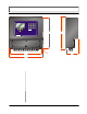
SOFTWARE UTILITIES Uploading Data from the Logger During the installation of UltraLink, a file called DatLog was installed and its icon will appear on the Desktop of the computer. Click on the icon to start the utility. The screen shown in Figure 4.11 will appear as the computer is attempting to establish communications with the logger module. Figure 4.11 Data Logger Initialization Connect the logger to the terminal strip (see Fig. 1.4).
SOFTWARE UTILITIES logger module and the uploading of the file data can take up to several minutes. The files will appear on the table, See Figure 4.12, in a list running from the earliest file to the latest file. Information regarding starting time and date and points collected will appear. If a file is selected, the time stamped data will appear on the strip chart located on the bottom of the window.
SOFTWARE UTILITIES The datalogger module contains a real-time clock that can be set by pressing the Clock button on the top task bar. See Figure 4.14. Activating the window compares the datalogger clock to the clock located in the PC. Adjustments can be made and uploaded to the logger. Figure 4.14 Setting Data Logger Clock Rev. 8/02 -4.
MULTICHANNEL OPERATION General Information Series TFXM is a multiple channel flow meter designed with maximum user flexibility in mind. The product can be configured as a simple flow meter, showing flow on multiple pipe simultaneously. It can also be used to perform mathematical manipulation of flow rates between pipes using its powerful, yet simple to use, algorithms. This manual will provide instructions as to configuration of the TFXM in the following scenarios: 1. 2. 3. 4. 5.
MULTICHANNEL OPERATION highlighting to the next line of the display. Pressing the (soft) SELECT key on the bottom line of the display will cause the display configuration to end and the setup will be saved. Multiple Pipe Configuration Multiple Pipe Flow Network The TFXM is designed to be the Primary (Master) flow controller in a network of Secondary (Slave) flow meters. The TFXM can be used to display flow information and configure up to 119 satellite flow meters connected on its RS485, two-wire network.
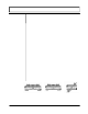
MULTICHANNEL OPERATION values are not being shown on the graphics display. Figure 5.1 Configuration for Multiple Pipe Readings Multiple Path Configuration Rev. 8/02 Multiple Path Flow Meter By applying more than one set of transducers radially around a pipe, accuracy can be improved in conditions where optimum straight pipe diameters are not available. Typical installations only involve two paths, but on large pipes several paths could be employed. See Figure 5.2 .
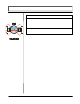
MULTICHANNEL OPERATION Figure 5.2 Multiple Path Flow Meter Summation Configuration Multiple Pipe Summation Flow Meter The TFXM can be used to measure the summation of several flow pipes. By entering coefficients of 1.00 for each channel, the sum of the channels will be displayed on the mathematically manipulated display configuration. See Figure 5.3. Figure 5.3 Summation Flow Meter Rev. 8/02 -5.
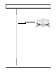
MULTICHANNEL OPERATION Difference Configuration Difference Flow Meter The difference of two pipes can be utilized to measure the flow in two pipes and calculate the flow rate in a third trunk line in a piping system. (The difference meter can also be applied to two ends of a piping system to display an alarm to leak between the two measuring points.) Apply a coefficient of +1.00 to one channel and a coefficient of –1.00 to the second channel.
APPENDIX
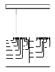
V V BSC MENU OUT1 MEN UNITS ENGLSH METRIC LINER SS ENGLSH (FPS) METRIC (MPS) XDCR MNT V W Z FL TYPE* TAP WATER SEWAGE KEROSENE GASOLINE FUEL OIL CRUDE OI PROPANE BUTANE OTHER PIPE OD ENGLSH (INCHES) METRIC (MM) PIPE WT ENGLSH (INCHES) METRIC (MM) PIPE MAT* CARBON S STAINLES CAST IRO DUCTILE COPPER PVC PVDF LOW PVDF HI ALUMINUM ASBESTOS FIBERGLASS OTHER PIPE SS ENGLSH (FPS) METRIC (MPS) PIPE R (RELATIVE ROUGHNESS) LINER T ENGLSH (INCHES) METRIC (MM) LINER TYPE* TAR EPOXY RUBBER MORTAR POLYPROPYLENE P
Fluid Sound Speeds Original Date: Revision: Revision Date: File: Fluid Acetate, Butyl (n) Acetate, Ethyl Acetate, Methyl Acetate, Propyl Acetone Alcohol Alcohol, Butyl (n) Alcohol, Ethyl Alcohol, Methyl Alcohol, Propyl (I) Alcohol, Propyl (n) Ammonia (35) Anlline (41) Benzene (29,40,41) Benzol, Ethyl Bromine (21) n-Butane (2) Butyrate, Ethyl Carbon dioxide (26) Carbon tetrachloride Chloro-benezene Chloroform (47) Diethyl ether Diethyl Ketone Diethylene glycol Ethanol Ethyl alcohol Ether Ethyl ether Ethyle
Linseed Oil .925-.939 Methanol (40,41) 0.79 Methyl alcohol (40,44) 0.79 Methylene chloride (3) 1.33 Methylethyl Ketone Motor Oil (SAE 20/30) .88-.935 Octane (23) 0.70 Oil, Castor 0.97 Oil, Diesel 0.80 Oil (Lubricating X200) Oil (Olive) 0.91 Oil (Peanut) 0.94 Paraffin Oil Pentane 0.626 Petroleum 0.876 1-Propanol (46) 0.78 Refrigerant 11 (3,4) 1.49 Refrigerant 12 (3) 1.52 Refrigerant 14 (14) 1.75 Refrigerant 21 (3) 1.43 Refrigerant 22 (3) 1.49 Refrigerant 113 (3) 1.56 Refrigerant 114 (3) 1.
TFX Error Codes Revised 2-22-2002 Code Number Description Correction 0001 Serial number not present Hardware serial number has become inoperative – system performance will not be influenced.
FPS TO GPM CROSS - REFERENCE (Schedule 40) Nominal I.D. Pipe INCH (Inches) 1 1.5 2 2.5 3 3.5 4 4.5 5 5.5 6 6.5 7 7.5 8 8.5 9 1 1.05 2.6989 4.0484 5.3978 6.7473 8.097 9.4462 10.796 12.145 13.490 14.844 16.190 17.540 18.890 20.240 21.590 22.941 24.290 1.25 1.38 4.6620 6.9929 9.3239 11.655 13.99 16.317 18.648 20.979 23.310 25.641 27.970 30.300 32.630 34.960 37.300 39.627 41.958 1.5 1.61 6.3454 9.5182 12.691 15.864 19.04 22.209 25.382 28.555 31.730 34.900 38.070 41.250 44.420 47.
FPS TO GPM CROSS - REFERENCE (Schedule 40) Nominal I.D. Pipe INCH (Inches) 1 1.5 2 2.5 3 3.5 4 4.5 5 5.5 6 6.5 7 7.5 8 8.5 9 18 16.88 697.52 1046.3 1395.0 1743.8 2093.0 2441.3 2790.1 3138.8 3488.0 3836.3 4185.0 4534.0 4883.0 5231.0 5580.0 5928.9 6277.7 20 18.81 866.14 1299.0 1732.0 2165.3 2598.4 3031.5 3464.6 3897.6 4330.7 4763.8 5196.8 5629.9 6063.0 6496.0 6929.1 7362.2 7795.3 24 22.63 1253.7 1880.0 2507.0 3134.1 3761.0 4387.8 5014.6 5641.5 6268.3 6895.1 7522.0 8148.8 8775.6 9402.
Addendum — Heat Flow Dynasonics Series TFX Heat Flow General The TFX flowmeter with the optional heat flow module installed is designed to measure the rate and quantity of heat delivered to a given building, area or heat exchanger. The instrument measures the volumetric flow rate of the heat exchanger liquid (water, water/glycol mixture, brine, etc.), the temperature at the inlet pipe and the temperature at the outlet pipe.
3. Place a small amount of heat sink compound on the pipe in the RTD installation location. See Figure 1. Press the RTD firmly into the compound. Fasten the RTD to the pipe with the included heater tape. 4. Route the RTD wires to an electrical junction box in close proximity to the installation location. Secure the RTD wires such that they will not be pulled on or abraded inadvertently. Replace the insulation on the pipe. 5. Route a cable from the electrical junction box back to the TFX flowmeter.
3. The RATE UNIT can be displayed as three different values; BTUs, CALs or Watts. Select the proper unit from the RATE UNIT list. Select the appropriate RATE INTERVAL from the list (seconds, minutes, hours, days). Be aware that the instrument can only display values as large as 99,999,999. 4. Select an appropriate TOTALIZER UNIT from the list; BTU, CAL, Watt. 5. In the SER MENU three values can be displayed that may aid in troubleshooting the heatflow instrument.
Limited Warranty and Disclaimer Dynasonics, div. of Racine Federated Inc. warrants to the end purchaser, for a period of one year from the date of shipment from our factory, that all new transmitters and transducers manufactured by it are free from defects in materials and workmanship. This warranty does not cover products that have been damaged due to normal use, misapplication, abuse, lack of maintenance, or improper installation.
GENERAL TERMS AND CONDITIONS OF SALES 1. PAYMENT – Terms of payment are effective from the actual date of invoice. If, in the Seller’s opinion, the financial condition of the Buyer at any time – or any other circumstances – do not justify the incurrence of production costs of shipment on the terms of payment specified, the Seller may require partial or full payment in advance. Payment terms are net 30 days unless otherwise stated on invoice. 2. F.O.B.
RETURN OF EQUIPMENT/SALES INFORMATION CONTACTS AND PROCEDURES Customer Service/Application Engineer: If you have a question regarding order status, placing an order, reviewing applications for future purchases, or wish to purchase a new flowmeter, please contact our new National Sales and Marketing Headquarters: DYNASONICS Division of Racine Federated, Inc.
8635 WASHINGTON AVENUE RACINE, WI 53406 TOLL-FREE IN NORTH AMERICA.: TEL: (800) 535-3569 FAX: (800) 732-8354 TEL: (262) 639-6770 FAX: (262) 639-2267 URL: www.dynasonics.