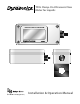
TFXL Clamp-On Ultrasonic Flow Meter for Liquids 06-TTM-UM-00158 (August 2012) Installation & Operation Manual
06-TTM-UM-00158 8/2012
TABLE OF CONTENTS QUICK-START OPERATING INSTRUCTIONS ...... 5 PART 3 - INPUTS/OUTPUTS .............................. 16 Q1 - Transducer Location Q2 - Pipe Preparation and Transducer Mounting (Integral DTTS and DTTC Transducers) (DTTN and DTTH Transducers) Q3 - Electrical Connections ............................................................... 6 POWER CONNECTIONS TRANSDUCER CONNECTIONS Q4 - Startup...........................................................................................
FIGURES Figure Q.1 - Transducer Mounting Configurations ...................... 5 Figure Q.2 - Transducer orientation ................................................ 6 Figure Q.3 - Power Connections Figure Q.4 - Remote Mount Connections ....................................... 7 Figure 1.1 - Ultrasound Transmission .............................................. 7 Figure 1.2 - Enclosure Dimensions ................................................... 8 Figure 1.3 - Transducer Connections .......................
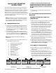
QUICK-START OPERATING INSTRUCTIONS This manual contains detailed operating instructions for all aspects of the TFXL instrument. The following condensed instructions are provided to assist the operator in getting the instrument started up and running as quickly as possible. This pertains to basic operation only. If specific instrument features are to be used or if the installer is unfamiliar with this type of instrument, refer to the appropriate section in the manual for complete details.
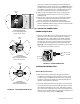
pipe, choose a flow meter mounting location within approximately 45-degrees of the side of the pipe. See Figure Q.2. Locate the flow meter so that the pipe will be completely full of liquid when flow is occurring in the pipe. Avoid mounting on vertical pipes where the flow is moving in a downward direction. 3) Apply a single ½” (12 mm) bead of acoustic couplant grease to the upstream transducer and secure it to the pipe with a mounting strap.
the sound crosses the pipe once. The selection of how transducers are mounted on opposite sides of the pipe and method is based on pipe and liquid characteristics which both have an effect on how much signal is generated. The flow meter operates by alternately transmitting and receiving a frequency modulated burst of sound energy between the two transducers and measuring the time interval that it takes for sound to travel between the two transducers.
Locate the transmitter within the length of transducer cable that was supplied with the TFXL system. If this is not possible, it is recommended that the cable be exchanged for one that is of proper length. Both transducer cables must be of the same length. NOTE: The transducer cable carries low level, high frequency signals. In general, it is not recommended to add additional cable to the cable supplied with the DTTN, DTTH, DTTS or DTTC transducers.
Wiring methods and practices are to be made in accordance with the NEC - National Electrical Code® - and/or other local ordinances that may be in effect. Consult the local electrical inspector for information regarding wiring regulations. TRANSDUCER CONNECTIONS When making connections to the field wiring terminals inside the flow meter, strip back the wire insulation approximately 0.25 inch (6 mm). Stripping back too little may cause the terminals to clamp on the insulation and not make good contact.
NOTE: The transducer cable carries low level, high frequency signals. In general, it is not recommended to add additional length to the cable supplied with the transducers. If additional cable is required, contact the factory to arrange an exchange for a transducer with the appropriate length of cable. Cables 100 to 990 feet (30 to 300 meters) are available with RG59 75 Ohm coaxial cable. If additional cable is added, ensure that it is the same type as utilized on the transducer.
Piping Configuration and Transducer Positioning Upstream Pipe Diameters Downstream Pipe Diameters * ** 24 5 Flow * ** * Pipe Material Liquid Composition Pipe Size Plastic (all types) Carbon Steel 2-4 in. (50-100 mm) Stainless Steel W-Mount 14 Flow Transducer Mount Mode Copper Ductile Iron 5 Not recommended Cast Iron ** Plastic (all types) 10 Flow * 5 Stainless Steel ** V-Mount 10 Flow * 4-12 in. (100-300 mm) Carbon Steel 5 4-30 in.
iterative process. Table 2.2 contains recommended mounting configurations for common applications. These recommended configurations may need to be modified for specific applications if such things as aeration, suspended solids, out of round piping or poor piping conditions are present. Use of the TFXL diagnostics in determining the optimum transducer mounting is covered later in this section.
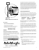
the transducers should be mounted 180 radial degrees from one another and at least 45 degrees from the top-deadcenter and bottom-dead-center of the pipe. See Figure 2.2. Also see Z-Mount Transducer Installation. On vertical pipes the orientation is not critical. ½” (12 mm) TOP OF PIPE 45° FIGURE 2.
NOTE: Mounting of high temperature transducers is similar to mounting the DTTN transducers. High temperature installations require acoustic couplant that is rated not to “flow” at the temperature that will be present on the pipe surface. DTTS/DTTC SMALL PIPE TRANSDUCER AND INTEGRAL MOUNT INSTALLATION The small pipe transducers are designed for specific pipe outside diameters.
Edit Calibration Points Model: DTTSJP-050-N000-N S/N: 39647 Delta-T: 391.53nS Uncal. Flow: 81.682 GPM Cal. Flow: 80 GPM Delta T: 391.53 ns Uncalibrated Flow: 81.682 Gal/Min. Calibrated Flow: 80.000 Gal/Min. OK tion of the mark. Move to the other side of the pipe and mark the pipe at the ends of the crease. Measure from the end of the crease (directly across the pipe from the first transducer location) the dimension derived in Step 2, Transducer Spacing. Mark this location on the pipe.
calculated transducer spacing. See Figure 2.13. Using firm hand pressure, slowly move the transducer both towards and away from the upstream transducer while observing signal strength. Clamp the transducer at the position where the highest signal strength is observed. Signal strength of between 5 and 98 is acceptable. The factory default signal strength setting is 5, however there are many application specific conditions that may prevent the signal strength from attaining this level.
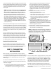
Supply Voltage - 7 VDC 0.02 OPTIONAL TOTALIZING PULSE SPECIFICATIONS = Maximum Loop Resistance 1100 OPTIONAL TFXL TOTALIZING PULSE OUTPUT 1000 Loop Load (Ohms) 900 Signal 1 pulse for each increment of the totalizers least significant digit.
For the TFXL this relationship is described by the following equation. The 60,000 relates to measurement units in volume/min. Measurement units in seconds, hours or days would require a different numerator. K factor 60,000 Full Scale Units EQUATION 3.
2) Double-click on the ULTRALINK icon. The first screen is the “RUN” mode screen (see Figure 4.2), which contains real-time information regarding flow rate, totals, signal strength, communications status, and the flow meter’s serial number. The COMM indicator in the lower righthand corner indicates that the serial connection is active. If the COMM box contains a red ERROR, click on the Communications button on the Menu bar and select Initialize.
Frequency 2 MHz 1 MHz Transducers All ½” thru 1½” Small Pipe and Tube 2” Tubing Transmission Modes Pipe Size and Type Selected by Firmware Specific to Transducer 2” ANSI Pipe and Selected by Copper Tube Firmware Specific to Transducer Standard and High Temp 2” and Greater W, V, and Z Speed and Absolute Viscosity into the appropriate boxes. The liquid’s Specific Gravity is required if mass measurements are to be made. FLOW TAB Flow Rate Units are selected from the drop-down lists.
will be in the Flow Rate Units. For unidirectional measurements, set Max Flow to the highest (positive) flow rate expected in the piping system. For bidirectional measurements, set Max Flow to the highest (positive) flow rate expected in the piping system. Low Flow Cutoff is provided to allow very low flow rates (that can be present when pumps are off and valves are closed) to be displayed as zero flow. Typical values that should be entered are between 1.0% and 5.
are examined by the Bad Data Rejection filter. The value is entered as a percentage of actual flow rate. For example, if the average flow rate is 100 GPM and the Flow Filter Hysteresis is set to 5%, a filter window of 95-105 GPM is established. Successive flow measurements that are measured within that window are recorded and averaged in accordance with the Flow Filter Damping setting. Flow readings outside of the window are held up in accordance with the Bad Data Rejection filter.
Flow at 4 mA / 0 Hz = -100.0 Flow at 20 mA / 1,000 Hz = 100.0 Calibration (Page 1 of 3) - Zero Flow If the meter were a TFXL, this setting would also set the span for the frequency output. At -100 GPM, the output frequency would be 0 Hz. At the maximum flow of 100 GPM, the output frequency would be 1,000 Hz, and in this instance a flow of zero would be represented by an output frequency of 500 Hz. 1. Make sure flow is at zero. 2. Wait for flow to stabilize. 3. Press to calibrate the zero offset.
Calibration (Page 2 of 3) - General Setup Target Dbg Data 1) Please establish a reference flow rate. Device Type: TFX 1FPS / 0.3MPS Minimum. 2) Enter the reference flow rate below. (Do not enter 0) Gal/MIN 3) Wait for flow to stablize. 4 Press the Set button. Calc Count: 54247 Raw Delta T (ns): -10.73 Gain: 430 Tx Delay: 413 Flow: Flow Filter: 80 Edit SS (Min/Max): 8.0/92.4 Export... Delta Time Sound Speed: 4900 Reynolds: 20.15 File Open... File Save... Cancel 1 2.
APPENDIX 06-TTM-UM-00158 8/2012 25
SPECIFICATIONS Liquid Types Most clean liquids or liquids containing small amounts of suspended solids Power Requirements 11-28VDC @ 0.25A Protection Reverse polarity, surge suppression Velocity 0.1…40 fps (0.03…12 mps) Inputs/Outputs 4-20mA Output (Standard Output) Totalizer Pulse Resolution 12-bit for all outputs Operation Normal state high; pulses low with display total increments Power Source Insertion loss 5V Max. 30mSec min. 900 Ohms Max. Pulse duration Loop impedance 2 mA max.
Part Number Construction Integral System 1/2"…2" (12…50 mm) DTFXL Part Number: - - N Display Options 1) No display 2) Rate & Toatalizer display Output 1) 4-20 mA & TTL Pulse 3) Totalizer Pulse Connector Options N) 1/2" Conduit Hole (2) A) Water-tight Cable Clamp(2) C) 4-Pin (male) Brad Harrison® Micro-Change® Connector D) 1/2" Flexible Conduit Connectors (2) Pipe Size A) 1/2" ANSI Pipe (DN 15) B) 3/4" ANSI Pipe (DN 20) C) 1" ANSI Pipe (DN 25) D) 1-1/4" ANSI Pipe (DN 32) G) 1/2" Copper E) 1-1/2" ANSI
TFXL ERROR CODES Revised 5-25-2009 Code Number Description Correction Warnings 0010 Signal Strength is below Signal Strength Cutoff entry Low signal strength is typically caused by one of the following: » Empty pipe » Improper programming/incorrect values » Improper transducer spacing » Non-homogeneous pipe wall 0011 Measured Speed of Sound in the liquid is greater than ±10% different than the value entered during meter setup Verify that the correct liquid was selected in the BASIC menu.
SENSING SURFACE: COUPLE TO PIPE WITH RTV OR SILICONE GREASE SUPPLIED, PER INSTALLATION MANUAL TFXD O&M. 990' MAX. (302 METERS) (RG-59/U COAX, BELDEN 9463, OR BELDEN 9463DB OR EQUAL ONLY) B1 10' MAX RED/BLUE NON-HAZARDOUS LOCATION I.S. WIRING 6.26 (MTG. HOLES) SAFE MODEL: 070-1010-002 I.S. Barrier-Ultrasonics SAFE RED/BLUE BLACK/CLEAR BLACK/CLEAR HAZ HAZ C1 I.S. MODULE PART NO. D070-1010-001 3.60 (MTG. HOLES) DYNASONICS I.S.
SENSING SURFACE: COUPLE TO PIPE WITH RTV OR SILICONE GREASE SUPPLIED, PER INSTALLATION MANUAL TFXD O&M. FLEXIBLE ARMORED CONDUIT SUITABLE FOR INCIDENTAL AND TEMPORARY SUBMERSION D002-1401-003 SEAL OFF CONDUIT PER INSTALLATION NOTES 6 & 7 990' MAX. (302 METERS) (RG-59/U COAX, BELDEN 9463, OR BELDEN 9463DB OR EQUAL ONLY) B1 TEE FITTING D002-1201-002 10' MAX I.S. WIRING 6.26 (MTG. HOLES) SAFE MODEL: 070-1010-002 I.S.
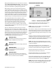
BRAD HARRISON® CONNECTOR OPTION O N 1 2 1 3 4 Signal Gnd. 4-20 mA Out Power Gnd. 11 - 28 VDC 2 1 3 4 Cable D005-0956-001 (Straight Connector) D005-0956-002 (90° Connector) Bulkhead Connector D005-0954-001 FIGURE A-7.
K-FACTORS EXPLAINED The K-factor (with regards to flow) is the number of pulses that must be accumulated to equal a particular volume of fluid. You can think of each pulse as representing a small fraction of the totalizing unit. An example might be a K-factor of 1000 (pulses per gallon). This means that if you were counting pulses, when the count total reached 1000, you would have accumulated 1 Gallon of liquid. Using the same reasoning each individual pulse represents an accumulation of 1/1000 of a gallon.
The calculation is a little more complex if velocity is used because you first must convert the velocity into a volumetric flow rate to be able to compute a K-factor. To convert a velocity into a volumetric flow, the velocity measurement and an accurate measurement of the inside diameter of the pipe must be known. Also needed is the fact that 1 US gallon of liquid is equal to 231 cubic inches. Example 3: Known values are: Velocity Inside Diameter of Pipe = = 4.3 ft/sec 3.
FLUID PROPERTIES Fluid Acetate, Butyl Acetate, Ethyl Acetate, Methyl Acetate, Propyl Acetone Alcohol Alcohol, Butyl Alcohol, Ethyl Alcohol, Methyl Alcohol, Propyl Alcohol, Propyl Ammonia Aniline Benzene Benzol, Ethyl Bromine n-Butane Butyrate, Ethyl Carbon dioxide Carbon tetrachloride Chloro-benezene Chloroform Diethyl ether Diethyl Ketone Diethylene glycol Ethanol Ethyl alcohol Ether Ethyl ether Ethylene glycol Freon R12 Gasoline Glycerin Glycol Isobutanol Iso-Butane Isopentane Isopropanol Isopropyl Alcoho
FLUID PROPERTIES (continued) Specific Fluid Gravity 20 °C Linalool Linseed Oil Methanol Methyl Alcohol Methylene Chloride Methylethyl Ketone Motor Oil (SAE 20/30) Octane Oil, Castor Oil, Diesel Oil (Lubricating X200) Oil (Olive) Oil (Peanut) Paraffin Oil Pentane Petroleum 1-Propanol Refrigerant 11 Refrigerant 12 Refrigerant 14 Refrigerant 21 Refrigerant 22 Refrigerant 113 Refrigerant 114 Refrigerant 115 Refrigerant C318 Silicone (30 cp) Toluene Transformer Oil Trichlorethylene 1,1,1 -Trichloroethane Turpent
SYMBOL EXPLANATIONS Caution—Refer to accompanying documents. FLOW METER INSTALLATION WARNING: EXPLOSION HAZARD - SUBSTITUTION OF COMPONENTS MAY IMPAIR SUITABILITY FOR CLASS I, DIVISION 2. WARNING: DO NOT CONNECT OR DISCONNECT EITHER POWER OR OUTPUTS UNLESS THE AREA IS KNOWN TO BE NON-HAZARDOUS. IMPORTANT NOTE: Not following instructions properly may impair safety of equipment and/or personnel. IMPORTANT NOTE: Must be operated by a Class 2 supply suitable for the location.
06-TTM-UM-00158 8/2012 37 1.315 1.660 1.900 2.375 2.875 3.500 4.000 4.500 5.563 6.625 8.625 10.75 12.75 14.00 16.00 18.00 20.00 24.00 30.00 36.00 42.00 48.00 3.5 4 5 6 8 10 12 14 16 18 20 24 30 36 42 48 Outside Diameter Nominal Pipe Size Inches 1 1.25 1.5 2 2.5 3 12.42 3.834 4.334 5.345 6.407 8.407 10.482 ID 1.185 1.53 1.77 2.245 2.709 3.334 0.165 0.083 0.083 0.109 0.109 0.109 0.134 Wall 0.065 0.065 0.065 0.065 0.083 0.083 SCH 5 29.37 35.37 12.39 13.50 15.50 17.50 19.50 23.50 3.760 4.
06-TTM-UM-00158 8/2012 Outside Diameter 1.315 1.660 1.900 2.375 2.875 3.500 4.000 4.500 5.563 6.625 8.625 10.75 12.75 14.00 16.00 18.00 20.00 24.00 30.00 36.00 42.00 48.00 Nominal Pipe Size Inches 1 1.25 1.5 2 2.5 3 3.5 4 5 6 8 10 12 14 16 18 20 24 30 36 42 48 11.626 12.814 14.688 16.564 18.376 22.126 7.813 9.750 ID 0.562 0.593 0.656 0.718 0.812 0.937 0.406 0.500 Wall SCH 60 29.00 35.00 41.00 47.00 11.75 13.00 15.00 17.00 19.00 23.00 3.364 3.826 4.813 5.761 7.625 9.75 ID 0.957 1.
06-TTM-UM-00158 8/2012 39 3” 2½” 2” 1½” 1¼” 1” ¾” 5⁄8” ½” 0.995 1.375 I.D. O. D. 0.109 2.907 I.D. 3.125 O. D. Wall 2.435 I.D. 2.625 O. D. 0.095 1.959 Wall 0.083 2.125 O. D. I.D. 1.481 I.D. Wall 0.072 Wall 1.625 0.065 Wall O. D. 1.125 O. D. 1.245 0.745 I.D. 0.065 0.065 Wall I.D. 0.875 O. D. Wail 0.652 I.D. 0.750 O. D. 0.049 0.527 I.D. Wall 0.049 0.625 K Wall O. D. Nominal Diameter 2.945 0.090 3.125 2.465 0.080 2.625 1.985 0.070 2.
06-TTM-UM-00158 8/2012 16” 14” 12” 10” 8” 6” 4” 3” 17.40 17.40 0.34 16.72 O.D. Wall I.D. 16.66 0.37 14.58 14.64 I.D. 0.36 15.30 0.33 15.30 O.D. 12.52 0.34 13.20 10.46 0.32 11.10 8.45 0.30 9.05 6.34 Wall 12.58 I.D. 13.20 O.D. 0.31 10.32 I.D. Wall 0.39 11.10 O.D. Wail 8.51 I.D. 9.05 0.27 O.D. Wall 6.40 I.D. 6.90 0.28 O.D. 0.25 4.28 I.D. Wall 0.26 4.80 O.D. Wall 3.46 I.D. 3.96 51 0.25 6.90 50 Wall O.D. Size (Inches) 16.60 0.
06-TTM-UM-00158 8/2012 41 20” 18” 16” 14” 12” 10” 8” 6” 4” 3” A 21.60 21.60 0.67 20.26 O.D. Wall I.D. 20.00 0.80 18.00 18.22 I.D. 0.75 19.50 0.64 19.50 O.D. 16.00 0.70 17.40 13.98 Wall 16.20 17.40 O.D. I.D. 14.16 I.D. 0.60 0.57 Wall 15.30 15.30 O.D. Wall 0.66 11.96 12.12 0.62 13.20 I.D. 13.20 O.D. 9.96 0.57 11.10 8.03 0.51 9.05 6.14 0.48 7.10 4.10 0.45 5.00 3.12 0.42 0.54 10.10 I.D. B 3.96 Wall 0.50 11.10 O.D. Wail 0.46 8.
06-TTM-UM-00158 8/2012
Badger Meter Warranty TFXL Clamp-on Ultrasonic Flow Meter for Liquids PRODUCTS COVERED The Badger Meter warranty shall apply to the Dynasonics TFXL clamp-on Ultrasonic flow meter for liquids (“Product”). MATERIALS AND WORKMANSHIP Badger Meter warrants the Product to be free from defects in materials and workmanship for a period of 12 months from the original purchase date. PRODUCT RETURNS Product failures must be proven and verified to the satisfaction of Badger Meter.
® C US Trademarks appearing in this document are the property of their respective entities. Due to continuous research, product improvements and enhancements, Badger Meter reserves the right to change product or system specifications without notice, except to the extent an outstanding contractual obligation exists. © 2012 Badger Meter, Inc. All rights reserved. info@dynasonics.com | www.dynasonics.com | www.badgermeter.