Series MFX Insertion MagProbe™ Flow Meter Operations & Maintenance Manual REV 01/11
TABLE OF CONTENTS Pages Quick-Start Operating Instructions Part 1 Introduction Introduction General 1.5 Applications 1.6 Model Matrix 1.7 - 1.8 Product Specifications Part 1 Installation MagProbe Connection Transmitter Power Connections Rev. 01/11 1.10 - 1.11 1.12 1.12 - 1.15 ISO-MOD Wiring and Configuration 4-20mA Output 1.17 Dual Control Relay 1.18 Rate Pulse Output 1.19 RS232C 1.20 RS485 1.21 DATALOGGER 1.22 Instrument Startup Part 2 Probe Installation 1.
TABLE OF CONTENTS Pages Programming Entries Part 3 Keypad Configuration Keypad Operation 3.1 - 3.2 BASIC MENU 3.3 - 3.7 OUTPUT MENU SECURITY MENU Part 4 Software Utilities 3.8 - 3.15 3.15 SERVICE MENU 3.15 - 3.17 DISPLAY MENU 3.17 - 3.18 Installation 4.1 Initialization 4.2 Configuration Pipe & Liquid 4.3 Flow Units 4.4 4.6 - 4.12 Outputs Setting Zero 4.13 Signal Quality 4.15 Data Logger Software 4.17 - 4.
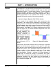
QUICK-START OPERATING INSTRUCTIONS This manual contains detailed operating instructions for all aspects of the MFX instrument. The following condensed instructions are provided to assist the operator in getting the instrument started up and running as quickly as possible. This pertains to basic operation only. If specific instrument features are to be used or if the installer is unfamiliar with this type of instrument, refer to the appropriate section in the manual for complete details.
QUICK-START OPERATING INSTRUCTIONS C. Measure the full length of the probe (E), calculate 12.5% of the pipe I.D. (A), obtain the pipe wall thickness (B) and measure the distance between the outer pipe wall and the top of the insertion fitting (C). D. Place a mark on the probe this is the proper distance from the top of the probe (D): D=E-A-B-C E. Insert the MagProbe into the insertion fitting and secure with the brass lock nuts—Series DMP2 - DMP6. F.
PART 1 - INTRODUCTION General The MagProbe is a point-velocity measuring device used primarily for measuring electrically conductive liquids, such as water and water-based liquids, in closed piping systems. The unit operates utilizing Faraday’s principle of magnetic conduction, whereby a moving conductor (the liquid) has a voltage imposed on it that is directly proportional to two variables—the strength of a local magnetic field and the velocity of the moving conductor.
PART 1 - INTRODUCTION The MFX MagProbe flow meter can be successfully applied on a wide range of metering applications. The simple to program transmitter allows the standard product to be used on pipe sizes ranging from 4 - 120 inch (100 - 3048 mm) pipe. A variety of liquid applications can be accommodated: potable water, chemicals, raw sewage, reclaimed water, cooling water, river water, plant effluent, etc.
PART 1 - INTRODUCTION User Safety The MFX employs modular construction and provides electrical safety for the operator. The display face contains voltages no greater than 10 Vdc. The display face swings open to allow access to user connections. As a general precaution, always disconnect electrical power before opening the instrument enclosure. Data Integrity Non-volatile memory retains all user-entered configuration values in memory even if power is lost or turned off.
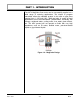
PART 1 - INTRODUCTION MagProbe Insertion Probe Rev. 01/11 -1.
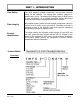
MagProbe Transmitter PART 1 - SPECIFICATIONS Rev. 01/11 -1.
PART 1 - TRANSMITTER INSTALLATION Transmitter Installation After unpacking, it is recommended to save the shipping carton and packing materials in case the instrument is stored or re-shipped. Inspect the equipment and carton for damage. If there is evidence of shipping damage, notify the carrier immediately. The enclosure should be mounted in an area that is convenient for servicing, calibration or for observation of the LCD readout. 1.
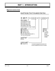
PART 1 - TRANSMITTER INSTALLATION Figure 1.5 - MFX Transmitter Installation Dimensions Rev. 01/11 -1.
PART 1 - TRANSMITTER INSTALLATION MagProbe Connections To access terminal strips for electronic connectors, loosen the two screws in the enclosure door and open the door. 1. Guide the MagProbe terminations through the transmitter conduit hole located in the bottom-center of the enclosure. Secure the MagProbe conduit with the supplied conduit nut if flexible conduit was ordered with the transducer.
PART 1 - TRANSMITTER INSTALLATION CAUTION: Any other wiring method may be unsafe or cause improper operation of the instrument. Do not run line power with other signal wires within the same wiring tray or conduit. NOTE: This instrument requires clean electrical line power. Do not operate this unit on circuits with noisy components (i.e. fluorescent lights, relays, compressors, variable frequency drives, etc.
PART 1 - TRANSMITTER INSTALLATION AC POWER CONNECTIONS 1. Verify that the jumpers at JP3 are properly oriented for the power supply. Verify that the jumpers at JP1 and JP2 are not present. 2. Connect L1, L2 and earth to the terminals referenced in Figure 1.7 on page 1.13. Phase and neutral connections to L1 and L2 are not polarized. Do not operate without an earth ground connection. 3. See Figure 1.8 for AC connection schematic. Wire gauges up to 14 AWG can be accommodated in the MFX terminal blocks.
PART 1 - TRANSMITTER INSTALLATION DC Power Supply DC POWER CONNECTIONS The MFX may be operated from a 9-28 Vdc source, as long as the source is capable of supplying a minimum of 3 Watts. 1. Verify that the jumpers are properly placed. See the wiring diagram located on the inside door of the MFX enclosure or see Figure 1.7 on page 1.13. The jumpers at JP3 should not be present and the jumpers at JP1 and JP2 will be in place.
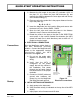
PART 1 - ISO-MOD General The MFX utilizes ISO-MODs for input and output functions. ISOMODs are epoxy encapsulated electronic input/output modules that are simple to install and replace in the field. See Figure 1.10. All modules are 2,500 V optically isolated from MFX power and earth grounds. This eliminates the potential for ground loops and reduces the chance of severe damage in the event of an electrical surge. Figure 1.
PART 1 - ISO-MOD 4-20 mA Output The 4-20 mA Output Module interfaces with most recording and logging systems by transmitting an analog current signal that is proportional to system flow rate. The 4-20 mA ISO-MOD may be configured via jumper selections for either an internally powered mode (current sourcing) Figure 1.11A or externally powered mode (current sinking) Figure 1.11B. Internal Power Configuration: Ensure that jumpers are in place at JP1 and JP2 on the module. See Figure 1.11A.
PART 1 - ISO-MOD Control Relay Two independent SPDT (single-pole, double-throw) Form C relays are contained in this module. The relay operations are user configured via software to act in either a flow rate alarm, signal strength alarm or totalizer/batching mode. The relays are rated for 200 Vac maximum and have a current rating of 0.5 A resistive load (175 Vdc @ 0.25 A resistive).
PART 1 - ISO-MOD Rate Pulse The Rate Pulse Output Module is utilized to transmit information to external counters and PID systems via a frequency output that is proportional to system flow rate. The frequency output range of the Rate Pulse Module is 0–2,500 Hz. This module has two types of outputs: one simulates the output of the coil of a turbine flow meter, and the other is an open-collector type that does not source voltage at its output. Both outputs may be connected simultaneously.
PART 1 - ISO-MOD RS232C The RS232C Module will interface with the serial communication ports of PCs, PLCs and SCADA systems that are used to monitor flow rate information in piping systems. A proprietary digital communications protocol is used for this communication. An explanation of the command structure is detailed in the Appendix of this manual. Flow rate, total, signal strength and temperature (if so equipped) can be monitored over the digital communications module.
PART 1 - ISO-MOD RS485 The RS485 Module allows up to 128 MFX systems to be placed on a single three-wire cable bus. All meters are assigned a unique one byte serial number that allows all meters on the cable network to be independently accessed. A proprietary digital communications protocol is used for this communication. An explanation of the command structure is detailed in the Appendix of this manual.
PART 1 - ISO-MOD Data Logger The 200,000 event data logger/electronic stripchart recorder can be configured to match most user applications. The logger stores timestamped, high resolution (16-bit) data at user selected intervals ranging from 1 to 1,000 seconds. Configuration of and data retrieval from the logger are detailed in Sections 3 and 4 of this manual. The module can be carried in a shirt pocket back to the office and plugged into a PC serial port via the module’s integral DB-9 connector.
PART 1 - INSTRUMENT STARTUP Before Starting the Instrument NOTE: The MFX flow meter system requires a full pipe of liquid before a successful startup can be completed. Do not attempt to make adjustments or change configurations until a full pipe is verified. Instrument Startup Procedure: 1. Verify that all wiring is properly connected and routed as described in Part 1 of this manual. 2. Verify that the MagProbe sensor is properly mounted as described in Part 2 of this manual. 3. Apply power.
PART 2 - MAGPROBE INSTALLATION After unpacking, it is recommended to save the shipping carton and packing materials in case the instrument is stored or re-shipped. Inspect the equipment and carton for damage. If there is evidence of shipping damage, notify the carrier immediately. MagProbe Mounting Considerations Step A Mounting Locations The DMP insertion probe that is utilized by the MFX flow meter system contains an electromagnet, electrodes and amplification circuitry.
PART 2 - MAGPROBE INSTALLATION 1 Table 2.1 - Straight Pipe Recommendations 1 The MFX system will provide repeatable measurements on piping systems that do not meet these requirements, but the accuracy of these readings may be influenced to various degrees. Rev. 01/11 -2.
PART 2 - MAGPROBE INSTALLATION Step B Hot-Tapped Installation The installation instructions cover hot-tapped installations (installations where it is required to install or remove the MagProbe without shutting down the process pressure). If the product is being installed without an isolation valve, ignore the steps that pertain to its installation. Figure 2.2 illustrates an exploded view of an isolation valve assembly and names the various components.
PART 2 - MAGPROBE INSTALLATION Step C Component Assembly These instructions call for the use of a drilling machine designed for drilling holes in pipes that are under pressure (for example, Muller Co., Decatur, Illinois manufactures products for this purpose). Procedures are as follows: 1. Verify that the line pressure within the pipe is within the rated limits of the pressure drilling machine, welded coupling or pipe saddle, valve and MagProbe to be used. 2.
PART 2 - MAGPROBE INSTALLATION Step D Probe Insertion Distances PROBE INSERTION Before inserting the MagProbe into the piping system, it is necessary to calculate the probe insertion depth that will place the measuring electrodes at the proper position in the pipe. In order to complete this calculation, some knowledge of the piping system must be known. Refer to the paragraphs that follow and Figure 2.3 for information regarding this process.
PART 2 - MAGPROBE INSTALLATION TO CALCULATE INSERTION DEPTH Measure and record the following linear distances: E = PROBE LENGTH Installation Measurements: DMP2 through DMP6 MagProbes = _______ C = INSERTION FITTING to PIPE WALL = _______ B = PIPE WALL THICKNESS = _______ A = 0.125 x PIPE ID = _______ D = INSERTION DEPTH = _______ D=E-C-B-A Figure 2.3 Installation Measurements Rev. 01/11 -2.
PART 2 - MAGPROBE INSTALLATION Step E Cable Routing PROBE CABLE Before inserting the MagProbe into the pipe, the sensor cables should be routed to the transmitter location. Locate the transmitter within the length of MagProbe cable that was supplied with the MFX system. If this is not possible, replace the entire length of interconnect cable with Belden® part number 9536, Dynasonics part number D005-1003-003 or equivalent.
PART 2 - MAGPROBE INSTALLATION Step F MagProbe Insertion DMP2 through DMP6 MAGPROBE INSERTION DMP2 through DMP6 1. Apply sealant to the 1-½" NPT threads of the insertion fitting assembly. Screw the assembly into the isolation valve and tighten with a 2-½" pump wrench. Final orientation of the two threaded rods on the MagProbe insertion fitting should be approximately perpendicular to the pipe’s axis. 2.
PART 2 - MAGPROBE INSTALLATION 4. Slowly open the isolation valve. When the valve is fully open, use a 9/16" wrench on the insertion nuts, alternately tightening each nut about two complete turns to avoid uneven seal loading—two 9/16" ratcheting wrenches can expedite this process. Repeat until the length of probe remaining above the seal fitting equals the “D” length calculated in step D.
PART 3 - KEYPAD CONFIGURATION General After installation of the MagProbe sensor and connection of appropriate power supplies to the MFX, keypad configuration of the instrument can be undertaken. All entries are saved in non-volatile FLASH memory and will be retained in the event of power loss. The DMFXD2 is configured through the keypad interface and the DMFXD1 is configured through a software utility at the Dynasonics factory.
PART 3 - KEYPAD CONFIGURATION 3. The ENTER key is pressed from the RUN mode to view the current software version operating in the instrument. x Used to access the configuration parameters in the various menus. x Used to initiate changes in configuration parameters. x Used to accept configuration parameter changes. Menu Structure The MFX software is structured using menus. A Map of the user interface has been included in the Appendix of this manual.
PART 3 - KEYPAD CONFIGURATION The following sections define the configuration parameters located in each of the menus. 1. BASIC MENU The BASIC menu contains all of the configuration parameters necessary to make the MFX operational. UNITS Selection IMPORTANT! K-factor Entry Rev. 01/11 UNITS ENGLSH METRIC Installs a global measurement standard into the operation of the instrument. The choices are either English or Metric measurements. x Select ENGLSH if all configurations (pipe sizes, etc.
PART 3 - KEYPAD CONFIGURATION Pipe Diameter PIPE OD -- Pipe Outside Diameter Entry ENGLSH (Inches) METRIC (Millimeters) Enter the pipe outside diameter in inches if ENGLSH was selected as UNITS; in millimeters if METRIC was selected. IMPORTANT NOTE: Charts listing popular pipe sizes have been included in the Appendix of this manual. Correct entries for pipe O.D. and pipe wall thickness are critical to obtaining accurate flow measurement readings.
PART 3 - KEYPAD CONFIGURATION Engineering Units—RATE RATE UNT -- Engineering Units for Flow Rate GALLONS - U.S. Gallons LITERS - Metric Liter MGAL - Millions of U.S. Gallons CUBIC FT - Cubic Feet CUBIC ME - Cubic Meters ACRE FT - Acre Feet OIL BARR - Oil Barrels (42 U.S. Gallons) LIQ BARR - Liquor Barrels (31.5 U.S. Gallons) FEET - Linear Feet METERS - Linear Meters Select a desired engineering unit for flow rate measurements.
PART 3 - KEYPAD CONFIGURATION Engineering Units—TOTAL Exponent TOTL E -- Flow Totalizer Exponent Value E-1 to E6 Utilized for setting the flow totalizer exponent. This feature is useful for accommodating a very large accumulated flow. The exponent is a “ 10 n” multiplier, where “n” can be from -1 ( 0.1) to +6 ( 1,000,000).Table 3.5 should be referenced for valid entries and their influence on the DMFX display. Table 3.5 - Totalizer Exponent Values Minimum Flow Rate Exponent Display Multiplier E-1 0.
PART 3 - KEYPAD CONFIGURATION Low Flow Cut-off FL C-OFF -- Low Flow Cut-off Percent of MAX RATE A Low Flow Cut-off entry is provided to allow very low flow rates (that can be present when pumps are off and valves are closed) to be displayed as Zero flow. Typical values that should be entered are between 1.0% and 5.0% of full-scale. System Damping DAMP PER -- System Damping Relative Percent Entry DAMP PER establishes a maximum adaptive filter value.
PART 3 - KEYPAD CONFIGURATION 2. OUTPUT #1 MENU 4-20mA ISO-MOD 4-20mA FL 4MA FL 20MA CAL 4MA CAL 20MA 4-20 TST Configured via jumper selections into either a passive or active transmission mode (see Section 2 for details), the 4-20 mA Output Module interfaces with virtually all recording and logging systems by transmitting an analog current signal that is proportional to system flow rate. Independent 4 mA and 20 mA span settings are established in software using the Flow Measuring Range entries.
PART 3 - KEYPAD CONFIGURATION For example, to span the 4-20mA output from 0 GPM to +100 GPM, with 12mA being 50 GPM, set the FL 4MA and FL 20MA inputs as follows: FL 4MA = 0.0 FL 20MA = 100.0 4-20mA Calibration The 4-20mA ISO-MOD is factory calibrated and should not require adjustment unless it is replaced. The CAL4MA entry allows fine adjustments to be made to the “zero” of the 4-20mA output. To adjust the 4mA output, an ammeter or reliable reference connection to the 4-20mA output must be present.
PART 3 - KEYPAD CONFIGURATION 4-20mA Test 4-20 TST - 4-20mA Output Test 4-20 Allows a simulated value to be output on from the 4-20mA output. By incrementing this value, the 4-20mA output will transmit the indicated current value. This feature can be utilized to confirm connectivity with chart recorders, data acquisition systems or other monitoring equipment. Rate Pulse/ Freq ISO-MOD RATE PULSE (Value) Flow at 0 Hz Flow at 2.5k Hz (FL 0H) (FL 2.
PART 3 - KEYPAD CONFIGURATION For example, in a bi-directional system, to span the 0 to 2.5k Hz output from –100 GPM to +100 GPM, with 1.25k Hz being 0 GPM, set the FL 100H and FL 10KH inputs as follows: FL 0H = –100.0 FL 25KH = 100.0 For example, to span the 0 to 2.5k Hz output from 0 GPM to +100 GPM, with 1.25k Hz being 50 GPM, set the FL 0H and FL 25KH inputs as follows: FL 0H = 0.0 FL 25KH = 100.
PART 3 - KEYPAD CONFIGURATION For example, if the Totalizer Exponent is set to E0 ( 1) and the Relay Multiplier is set to 1, then the relay will pulse each time the totalizer increments one count, or each single, whole measurement unit totalized. If the Totalizer Exponent is set to E2 ( 100) and the Relay Multiplier is set to 1, then the relay will pulse each time the display totalizer increments or once per 100 measurement units totalized.
PART 3 - KEYPAD CONFIGURATION RS232C Module ISO-MOD RS232C Baud Rate 1200 Baud 2400 Baud 9600 Baud 19,200 Baud (RS232 BA) (1200) (2400) (9600) (19200) The RS232C Module can be interfaced with serial communication ports of PCs, PLCs and SCADA systems. This module runs a proprietary digital protocol, detailed in the Appendix of this manual, that is used to monitor flow rate information in piping systems.
PART 3 - KEYPAD CONFIGURATION ADDRESS Each MFX connected on the communications bus must have an unique address number assigned. Address 127 is a universal address that will result in all MFX instruments on the network responding simultaneously—regardless of address—resulting in CRC errors. Only select address location 127 if one meter is on the network. Data Logger Option ISO-MOD DATALOGGER (Value) LOGGING INTERVAL From the OUTPUT 1 menu, select the time INTERVAL between readings.
PART 3 - KEYPAD CONFIGURATION 3. SECURITY MENU The SEC MENU allows the user to make password revisions, reset the flow totalizer and reset the transmitter microprocessor. Totalizer RESET TOT RES NO YES Select YES to reset the Positive, Negative and Net flow totalizer/ accumulator to Zero. System RESET SYS RSET NO YES Select YES to initiate a microprocessor reset. All system configurations and totalizer values will be maintained.
PART 3 - KEYPAD CONFIGURATION Substitute Flow Entry SUB FLOW - Substitute Flow Substitute Flow or SUB FLOW is a value that the analog outputs and the flow rate display will be driven at when an error condition in the flow meter occurs. The typical setting for this entry is a value that will make the instrument display zero flow during an error condition. TABLE 3.2 below lists some typical settings to achieve “Zero” with respect to MIN and MAX FLOW settings. TABLE 3.
PART 3 - KEYPAD CONFIGURATION Factory Default Zero Calibration D-FLT 0 -- Reverting to Factory Default Zero Correction Factor COR FTR -- Universal Correction Factor If the flow in a piping system cannot be shutoff, allowing the SET ZERO procedure described above to be performed, the factory default zero should be utilized. To utilize the D-FLT 0 function, simply press ENTER, then press an ARROW key to display YES on the display and then press ENTER.
PART 3 - KEYPAD CONFIGURATION Totalizer Display Mode TOTAL -- Totalizer Mode NET POS NEG BATCH Select NET to display the net difference between the positive direction and negative direction totalizers. Select POS to only view the positive direction totalizer. Select NEG to only view the negative direction totalizer. Select the BATCH totalizer to configure the totalizer to count up to a value that is entered as BTCH MUL (described on the following page).
PART 4 - SOFTWARE UTILITIES The MFX flow meter is supported by a troubleshooting software utility called ULTRALINK™. While ULTRALINK™ was developed to be utilized with Dynasonics Series TFX ultrasonic flow meters, the utility does have features that can assist MFX users in troubleshooting, configuration and calibration of the insertion magnetic flow meter system.
PART 4 - SOFTWARE UTILITIES Initialization 1. Connect communications cable, Dynasonics p/n D005-2115-001, to a PC communication port and point the communicator at the MFX infrared window, located in the lower right-hand corner of the meter front panel. Alternately, connect the PC communications port directly to an optionally installed RS232C or RS485 module located within the MFX flow meter. 2. Double-click on the ULTRALINK™ icon. The first screen is the “RUN-mode” screen (see Figure 4.
PART 4 - SOFTWARE UTILITIES Pipe and Liquid Configuration Click on the button labeled Configuration for updating flow range, liquid, pipe and I/O operating information. The first screen that appears after clicking the Configuration button is the BASIC tab. See Figure 4.2. Figure 4.2 Basic Tab 1. BASIC TAB - see Figure 4.2 x General Units allows selection of either English (U.S.) or Metric units of measure. If measurements of the pipe are to be entered in inches, select English.
PART 4 - SOFTWARE UTILITIES x Liner Thickness (entry becomes available when a Liner Material is selected) enter this value in inches for English units or millimeters for Metric units. x Fluid Type does not pertain to the MFX product. Flow Units Configuration 2. FLOW TAB - see Figure 4.3 x Flow Rate Units are selected from the pull-down lists. Select an appropriate rate unit and time from the two lists. x Totalizer Units are selected from pull-down lists.
PART 4 - SOFTWARE UTILITIES Exponent Display Multiplier E-1 0.1 (decimal is moved on display) E0 1 (no multiplier) E1 10 E2 100 E3 1,000 E4 10,000 E5 100,000 E6 1,000,000 TABLE 4.1 Totalizer Exponent Values x MAX Flow is used by the MFX to establish filter settings in its operating system. Enter a flow rate that is the maximum, positive flow rate anticipated within the system. x The Damping value is increased to increase stability of the flow rate readings.
PART 4 - SOFTWARE UTILITIES 3. ADVANCED TAB - does not pertain to MFX Output Configuration 4. OUTPUT TAB - see Figure 4.4 The entries made in the Output tab establish input and output calibration and ranges for the ISO-MOD module installed in the MFX flow meter. If an optional module was ordered from and installed at the Dynasonics factory, the Output tab will contain information and configuration for that module.
PART 4 - SOFTWARE UTILITIES 4-20 mA Module Configuration If the 4-20 mA output has been installed, the screen shown in Figure 4.4 on page 4.6 will appear in ULTRALINK™ at the OUTPUT tab: x Flow @4mA and Flow @20mA set the span of the 4-20 mA output. The entry is made in the same flow measurement units that were entered in the Flow tab. The output can be set to span across zero (4 mA can be set to a negative flow value) so that the module will output bi-directional flow.
PART 4 - SOFTWARE UTILITIES Relay Module Configuration If the Dual Relay output has been installed into the MFX flow meter, the screen shown in Figure 4.5 will appear in ULTRALINK™ at the OUTPUT tab. Each relay can be configured separately for one of four operations: Batch/Totalizer, Flow Rate, Signal Strength or Error. Figure 4.
PART 4 - SOFTWARE UTILITIES x Flow Rate Relay configuration permits relay changeover at two separate flow rates allowing operation with an adjustable switch deadband. Figure 4.6 illustrates how the setting of the two set points influences Rate Alarm operation. Figure 4.6 Single-point Alarm Operation A single-point flow rate alarm utilizes the ON> setting slightly higher than the OFF< setting—allowing a switch deadband to be established.
PART 4 - SOFTWARE UTILITIES Rate Pulse Module Configuration The Rate Module is utilized to transmit information to external counters and PID systems via a frequency output that is proportional to flow rate. The standard output of the module is 0-2,500 Hz, which corresponds to the flow rate span entered by the user. The Rate module configuration screen is shown in Figure 4.7. x Flow @0Hz and Flow @1/2.5KHz set the span of the Rate pulse output.
PART 4 - SOFTWARE UTILITIES RS232 Configuration The RS232 configuration window permits the selection of communications baud rate. Match this baud rate to that of the instrument with which the MFX will be required to communicate. Figure 4.8 shows the RS232 configuration screen. Figure 4.8 RS232 Configuration Rev. 01/11 -4.
PART 4 - SOFTWARE UTILITIES RS485 Configuration The RS485 configuration window permits the selection of communications baud rate and mode of the particular MFX instrument in the network. Figure 4.9 shows the RS485 configuration screen. Figure 4.9 RS485 Configuration x All MFX instruments on a single network must operate at the same Baud rate—9600 baud is typical. x Select the Mode of the MFX—either Master or Slave. Each network may have one Master and as many as 126 Slaves. Rev. 01/11 -4.
PART 4 - SOFTWARE UTILITIES Setting Zero on a Flowing Pipe Calibrating Zero on a Flowing Pipe ULTRALINK™ provides a means to calibrate “zero” flow on a pipe where the flow in the pipe cannot be shut off or blocked. To achieve optimum results, the flow in the pipe must be steady during the period when the calibration is performed. The procedure will take several minutes.
PART 4 - SOFTWARE UTILITIES Wait for Stable Reading Figure 4.11 Setting Zero Flow 5. Enter a value in the Set -> box that is equal to: New Set -> = (Forward reading - Reverse reading)/2 + Set -> 6. Enter the new calculated Set -> value into the box, ensuring to use a value of proper polarity—either positive or negative. 7. Press Next and then Finish on Page 3 of 3. Saving Meter Configuration on a PC The complete configuration of the flow meter can be saved from the Configuration screen.
PART 4 - SOFTWARE UTILITIES Signal Quality The Diagnostics screen provides valuable information regarding the signal-to-noise ratio (flow meter data quality). The two lines represent the voltage measurement across the electrodes with the magnet biased with forward polarity and the other line with the magnet biased with negative polarity. The separation between the lines increases with flow velocity and as a line reaches the top or bottom axis will roll over to the opposite axis.
PART 4 - SOFTWARE UTILITIES An example of signals that will provide good reading stability are shown in Figure 4.13. Figure 4.13 Good Diagnostic Signal Rev. 01/11 -4.
PART 4 - SOFTWARE UTILITIES Using the Data Logger Software During the installation of ULTRALINK™, a file called Dynasonics DatLog was installed and the utility will be located in the Dynasonics Program section of the computer. Run the DatLog program to start the utility. The screen shown in Figure 4.14 will appear as the computer is attempting to establish communications with the logger module. Figure 4.
PART 4 - SOFTWARE UTILITIES Figure 4.15 Logger Files Saving Logger Files to a PC To save the file to a computer, select the file from the file table and click the Save button located on the top task bar; see Figure 4.16 on page 4.19. Datalog saves the files in .csv (comma separated value) format. These files can be opened in programs such as Microsoft Excel® or Corel® Quattro Pro® for manipulation or graphical purposes.
PART 4 - SOFTWARE UTILITIES Figure 4.16 Saving Data Files Figure 4.17 Setting the Clock Rev. 01/11 -4.
NOTES
APPENDIX
RS232 COMMUNICATIONS PROTOCOL RS232 PROTOCOL The RS232 works on a simple command data structure.
RS232 COMMUNICATIONS PROTOCOL bbc generation: the bbc byte is generated by summing without overflow all characters in the transmission prior to the bbc byte excluding the [:] The bbc byte is then subtracted from ffh and added to 01h. The incoming bbc byte is compared to the calculated bbc. NVD structure: The non-volatile data is contained in a data structure as listed below: Care must be taken when presetting the NVD registers as there is no error checking involved in presetting of these values.
Outside Diameter 1.315 1.660 1.900 2.375 2.875 3.500 4.000 4.500 5.563 6.625 8.625 10.75 12.75 14.00 16.00 18.00 20.00 24.00 30.00 36.00 42.00 48.00 Nominal Pipe Size Inches 1 1.25 1.5 2 2.5 3 3.5 4 5 6 8 10 12 14 16 18 20 24 30 36 42 48 12.42 3.834 4.334 5.345 6.407 8.407 10.482 ID 1.185 1.53 1.77 2.245 2.709 3.334 0.165 0.083 0.083 0.109 0.109 0.109 0.134 Wall 0.065 0.065 0.065 0.065 0.083 0.083 SCH 5 29.37 35.37 12.39 13.50 15.50 17.50 19.50 23.50 3.760 4.260 5.295 6.357 8.329 10.
Outside Diameter 1.315 1.660 1.900 2.375 2.875 3.500 4.000 4.500 5.563 6.625 8.625 10.75 12.75 14.00 16.00 18.00 20.00 24.00 30.00 36.00 42.00 48.00 Nominal Pipe Size Inches 1 1.25 1.5 2 2.5 3 3.5 4 5 6 8 10 12 14 16 18 20 24 30 36 42 48 11.626 12.814 14.688 16.564 18.376 22.126 7.813 9.750 ID 0.562 0.593 0.656 0.718 0.812 0.937 0.406 0.500 Wall SCH 60 29.00 35.00 41.00 47.00 11.75 13.00 15.00 17.00 19.00 23.00 3.364 3.826 4.813 5.761 7.625 9.75 ID 0.957 1.278 1.500 1.939 2.323 2.900 0.
16” 14” 12” 10” 8” 6” 4” 3” 51 4.28 6.90 I.D. O.D. 17.40 17.40 0.34 16.72 O.D. Wall I.D. 16.66 0.37 14.58 14.64 0.36 15.30 I.D. 15.30 O.D. 12.52 0.33 12.58 I.D. 0.34 13.20 10.46 0.32 11.10 8.45 Wall 0.31 13.20 Wall O.D. 11.10 O.D. 10.32 8.51 I.D. I.D. 0.27 0.39 9.05 O.D. Wall Wail 9.05 6.40 I.D. 0.30 6.34 0.25 Wall 0.28 0.26 4.80 O.D. Wall 3.46 I.D. 3.96 0.25 6.90 50 Wall O.D. Size (Inches) 52 16.60 0.40 17.40 14.52 0.39 15.
20” 18” 16” 14” 12” 10” 8” 6” 4” 3” A 0.67 20.26 I.D. 21.60 O.D. Wall 0.64 19.50 O.D. 18.22 16.20 I.D. I.D. 0.60 Wall 17.40 17.40 O.D. Wall 20.00 0.80 21.60 18.00 0.75 19.50 16.00 0.70 13.98 14.16 0.66 15.30 I.D. 15.30 O.D. 11.96 0.57 12.12 I.D. 0.62 13.20 9.96 0.57 11.10 8.03 Wall 0.54 13.20 O.D. Wall 0.50 11.10 O.D. 10.10 8.13 I.D. I.D. 0.46 Wail 9.05 9.05 O.D. Wall 0.51 6.14 6.02 I.D. 0.48 7.10 4.10 0.45 5.00 3.12 0.42 0.
5.05 62.430 93.645 124.86 156.07 6.06 89.899 134.85 179.80 224.75 7.98 155.89 233.83 311.78 389.72 10.02 245.78 368.67 491.56 614.45 11.94 348.99 523.49 697.99 872.49 1047.0 1221.5 1396.0 1570.5 1745.0 1919.5 2094.0 2268.0 2443.0 2617.0 2792.0 2966.5 3141.0 13.13 422.03 633.04 844.05 1055.1 1266.0 1477.1 1688.1 1899.1 2110.0 2321.1 2532.0 2743.0 2954.0 3165.0 3376.0 3587.2 3798.2 15.00 550.80 826.20 1101.6 1377.0 1652.0 1927.8 2203.2 2478.6 2754.0 3029.4 3305.0 3580.0 3856.0 4131.0 4406.0 4681.8 4957.
47.99 5637.8 8457.0 11276 14095 53.98 7133.1 10700 14266 17833 60.09 8839.2 13259 17678 22098 72.10 12726 19089 25451 31814 84.10 17314 25971 34628 43285 48 54 60 72 84 60600 44540 30937 24966 19732 14579 FPS TO GPM: GPM = (PIPE ID)² X VELOCITY IN FPS X 2.45 GPM TO FPS: FPS = GPM (ID)² X 2.
Limited Warranty and Disclaimer Dynasonics, division of Racine Federated Inc. warrants to the end purchaser, for a period of one year from the date of shipment from the factory, that all new transmitters and transducers manufactured by it are free from defects in materials and workmanship. This warranty does not cover products that have been damaged due to misapplication, abuse, lack of maintenance or improper installation.
GENERAL TERMS AND CONDITIONS OF SALES 1. PAYMENT – Terms of payment are effective from the actual date of invoice. If, in the Seller’s opinion, the financial condition of the Buyer at any time – or any other circumstances – does not justify the incurrence of production costs of shipment on the terms of payment specified, the Seller may require partial or full payment in advance. Payment terms are net 30 days unless otherwise stated on invoice. 2. F.O.B.
RETURN OF EQUIPMENT/SALES INFORMATION CONTACTS AND PROCEDURES Customer Service/Application Engineer: If you have a question regarding order status, placing an order, reviewing applications for future purchases, or wish to purchase a new flow meter, please contact our new National Sales and Marketing Headquarters: DYNASONICS Division of Racine Federated Inc.
8635 Washington Avenue Racine, WI 53406 Toll-Free in U.S. and Canada: Tel: (800) 535-3569 Fax: (800) 732-8354 Tel: (262) 639-6770 Fax: (262) 639-2267 www.dynasonics.com DYNASONICS is a registered trademark of Racine Federated Inc. MagProbe and Ultralink are trademarks of Racine Federated Inc. BELDEN is a registered trademark of Belden Technologies, Inc. COREL and QUATTRO PRO are registered trademarks of Corel Corporation. NATIONAL ELECTRICAL CODE is a registered trademark of NFPA.