
User Manual


06-DPP-UM-00147 02/12 45
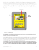
ISOMOD DUAL RELAY CONFIGURATION
DUAL RELAY
RELAY 1 AND RELAY 2
NONE
TOTAL
FLOW
OFF <
ON >
ERRORS
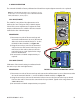
Two independent SPDT (single-pole, double-throw, Form C) relays are contained in this module. The re-
lay operations are user congured via the keypad to act in either a total pulse output, ow rate alarm or
error alarm mode. The relays are rated for 200 VAC maximum and a have current rating of 0.5 A resistive
load (175 VDC @ 0.25 A resistive). It is highly recommended that a secondary relay be utilized whenever
the Control Relay ISO-MOD is used to control inductive loads such as solenoids and motors.
TOTALIZER RELAY
TOTAL mode congures the relay to output a 50 mSec pulse (contact changeover) each time the display
totalizer increments.
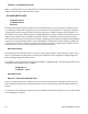
FLOW RATE RELAY
Flow Rate Relay conguration permits relay changeover at two separate ow rates allowing operation
with an adjustable switch deadband. Figure 4.3 illustrates how the setting of the two set points inu-
ences Rate Alarm operation.
A single-point ow rate alarm would place the ON> setting slightly higher than the OFF< setting – allow-
ing a switch deadband to be established. If a deadband is not established, switch chatter (rapid switch-
ing) may result if the ow rate is very close to the switch point.
Minimum
Flow
Maximum
Flow
Output ON
Set OFF
Set ON
Deadband
Output OFF
FIGURE 4.3 SINGLE POINT ALARM OPERATION