
User Manual


44 06-DPP-UM-00147 02/12
420TEST 420 MA OUTPUT TEST
Allows a simulated value to be output from the 4-20 mA output. By incriminating this value, the 4-20 mA
output will transmit the indicated current value.
ISOMOD RATE PULSE
FLOW 0HZ (Value)
FL MAXHZ (Value)
RATE TST
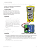
The Rate Pulse Output Module is utilized to transmit information to external counters and PID systems
via a frequency output that is proportional to system ow rate. Independent Zero and Span settings are
established in memory using the ow measuring range entries. Output resolution of the module is 12-
bits (4096 discrete points) and the maximum output frequency setting is 2,500 Hz. The module has two
output modes, turbine meter simulation and “open collector”. The turbine meter simulation sources a
non-ground referenced saw-tooth waveform with a maximum peak amplitude of approximately 500 mV
p-p. The open-collector output utilizes a 0.21 Ohm MOSFET output that is rated to operate at 100 V and
1 A maximum. If the open-collector output type is utilized, an external voltage source and limit resistor
must be present. See Part 1 of this manual for connection information.
RATE PULSE SPAN
The FLOW 0HZ and FL MAXHZ entries are used to set the span of the 0-2.5 kHz frequency output. These
entries are volumetric rate units that are equal to the volumetric units congured as Engineering Rate
Units and Engineering Units Rate Interval.
For example, to span the 0-2.5 kHz output from 0 GPM to +100 GPM, with 1.25 kHz being 50 GPM, set the
FLOW 0HZ and FL MAXHZ values as follows:
FLOW 0HZ = 0
FL MAXHZ = 100.0
RATE PULSE TEST
RATE TST RATE PULSE OUTPUT TEST
Allows a simulated value to be output from the rate pulse output. By incrementing this value, the rate
pulse output will transmit the indicated frequency in terms of percentage of the maximum output fre-
quency.
For example, if the maximum output frequency is 2500 Hz, increment the displayed value to 50 to output
a test frequency of 1250 Hz.