
User Manual


42 06-DPP-UM-00147 02/12
CONFIGURE I/O MODULE 1
CFG MOD1 -- Congure I/O Module 1 (Choice)
YES
NO
This prompt allows access to the setup parameters associated with installation of the optional ISO-MOD
interface modules. If NO is selected, the unit will skip ahead to CFG MOD2. If YES is selected, congura-
tion and calibration of the module installed in the rst position is accessible.
MODULE TYPE
MOD TYPE-- Module Type (Choice)
NONE No Module Installed
4-20MA 4-20mA Analog Output
RATE Rate Pulse Output
RELAY Relay Output
Select the type of module installed from the list.
ISO MOD 420 mA
ISO-MOD -- 4-20 mA
FLOW 4MA
FLOW 20MA
CAL 4MA
CAL 20MA
4-20 TEST
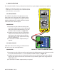
Congured via jumper selections for either a passive (current sinking) or active (current sourcing) trans-
mission mode (see Part 3 for details), the 4-20 mA Output Module interfaces with virtually all recording
and logging systems by transmitting an analog current signal that is proportional to system ow rate.
Independent 4 mA and 20 mA span settings are established in memory using the ow measuring range
entries. These entries can be set anywhere in the measuring range of the instrument. Output resolution
of the module is 12-bits (4096) discrete points) and the module can drive up to 800 Ohms of lead with its
internal 24 V isolated power source.
420 MA SPAN
The FLOW 4MA and FLOW 20MA entries are used to set the span of the 4-20 mA analog output. These
entries are volumetric rate units that are equal to the volumetric units congured as Engineering Rate
Units and Engineering Units Rate Interval.
For example, to span the 4-20 mA output from 0 GPM to +100 GPM, with 12 mA being 50 GPM, set the
FLOW 4MA and FLOW 20MA values as follows:
FLOW 4MA = 0.0
FLOW 20MA = 100.0