
User Manual


06-DPP-UM-00147 02/12 33
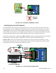
INTERNAL POWER CONFIGURATION
Ensure that jumpers are in place at JP1 and JP2 on the module – reference Figure 3.10B. In this congu-
ration, the 4-20 mA output is driven from a +24 VDC source located within the DFX ow meter. The 24
VDC source is isolated from DC ground and earth ground connections within the DFX instrument. The
module can accommodate loop loads up to 800 Ohms in this conguration.
NOTE: The +24 internal supply, if congured to power the 4-20 mA output, shares a common ground with another ISO-MOD (if
installed). If another module is connected to earth ground, a ground loop may occur. The solution to this problem is to congure
the 4-20 mA module for external power and utilize an external isolated supply to power the 4-20 mA loop.
EXTERNAL POWER CONFIGURATION
Remove the two jumpers located at JP1 and JP2 on the module – reference Figure 3.10C. In this con-
guration the 4-20 mA module requires power from an external DC power supply. The voltage of the
external power source must be sucient to power the module and drive the loop load. The loop loss
attributed to the ISO-MOD is 7 VDC, so the minimum voltage required to power a loop can be calculated
using the following formula:
Loop voltage (min) = (loop load Ohms × 0.02) + 7
OUT (-)
IN (
+
)
I/O: 4-20 mA
P.N. D020-1045-100
ISO-MOD
JP2
JP1
INT PWR EXT PWR
Use Both
Jumpers
RTU/PLC
MONITOR
4-20 mA IN (+)
4-20 mA OUT (-)
FIGURE 3.10B INTERNALLY POWERED 420 mA